Main components:
Engines general
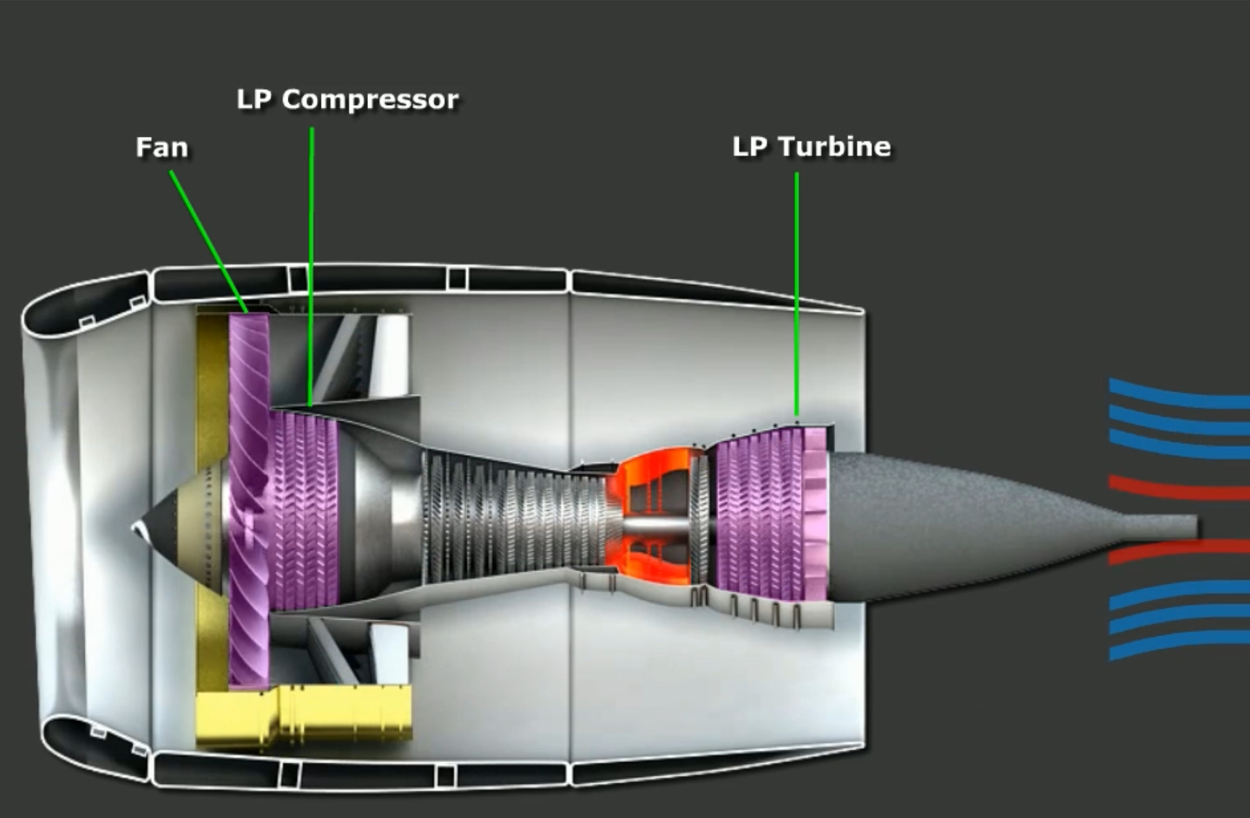
The 737NG is powered by two CFM56-7 high bypass, dual rotor, axial flow turbofans. Each engine contains the following sections:
- Fan section
- Compressor section
- Combustion chamber
- Turbine section
- Exhaust
The dual-rotor turbine consists of an N1 shaft and an N2 shaft, which are mechanically independent.
Each engine contains an accessory drive on the left side. It is driven by the N2 turbine, and it contains: ?
- Oil scavenge pump,
- Two engine fuel pumps
- IDG
- Engine air starter
- Hydraulic pump
- Oil/Fuel heat exchanger
- EEC alternator
N1 Rotor
The N1 rotor consists of: ?
- N1 Fan
- LP Compressor (booster)
- 4 stage low pressure turbine.
The N1 Fan and booster is a 4-stage compressor, bringing the total N1 compressors to 8.
Air from the N1 fan is split into two sections: primary and secondary (or bypass) air. About 20% of the airflow is primary air and is used for combustion, while the remaining 80% flows outside the core and is exhausted to provide most of the engine thrust.
N2 Rotor
The N2 rotor consists of: ?
- 9-stage high pressure compressor
- High pressure single stage turbine
The HP compressor increases the pressure of the air before its sent to the combustion chamber. Pneumatic air is taken from the 5th and 9th stages of the HP compressor.
The main purpose of the high pressure turbine is to use its mechanical energy to turn the HP compressor and the accessory drive, which is located on the left side of each engine.
Basic Engine Controls
Thrust Levers
The forward thrust lever position is sent as an angular value to the EEC, which in turn uses the signals to control the engines. The levers themselves can by controlled manually or by the auto-throttle system by two individual servo motors.
Note: not all autothrottle settings command movement of the thrust levers. in THR HLD or ARM modes, the servo motors are de-energised and the pilot can manually adjust thrust.
The TO/GA switches are located on the aft portion of the levers, while the autothrottle DISENGAGE switches are on the side of each thrust lever handle.
The reverse thrust levers are located just in front of the forward thrust levers. There is an interlock that prevents reverse levers to be operated at the same time as the forward thrust levers. The forward thrust levers must be in the full idle position for the reverse thrust lever to function.
The reverse thrust lever has 4 detents:
- Stowed
- Idle Detent
- Detent No. 1
- Detent No. 2 → Sufficient reverse thrust for normal operations.
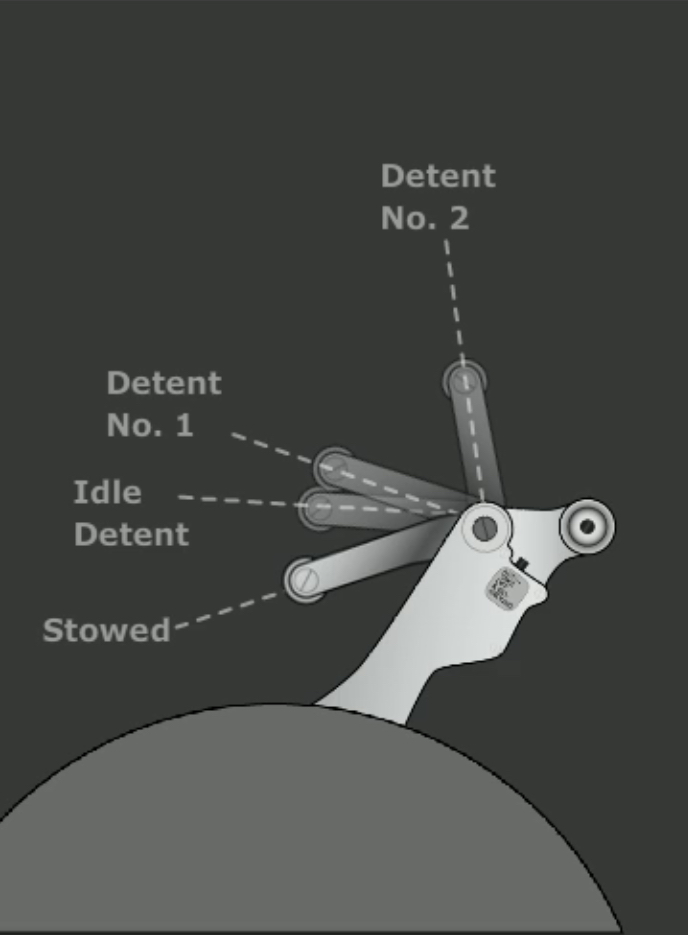
The Idle Detent blocks the reverse thrust lever until the related thrust reverser is more than 60% deployed. Moving the lever forward past detent No. 1 initiates the command to stow the reverser.
Engine Start / Ignition
Just below the forward thrust levers are the Engine Start Levers. These are two position levers: CUTOFF and IDLE.
When they are placed in IDLE during engine start, the ignition system is energised through the EEC. When this happens, the spar fuel and engine fuel shutoff valves are electrically opened to introduce fuel.
When moved to CUTOFF, both spar and engine valves are closed and the ignition system is de-energised.
The ignition system has two independent igniter plugs in each engine. The left plug receives power from the AC Transfer bus, while the right one receives it from the AC Standby bus.
The ENGINE START panel contains an IGN switch labelled:
- BOTH → Selects both igniters for both engines
- IGN L → Selects left igniter for both engines
- IGN R → Selects right igniter for both engines
With the ENGINE START switch positioned to GRD the engine starter engages the motors the engine. Ignition and fuel is supplied to the engine combustor when the Start Lever is mode to the IDLE position.
The igniters do not operate when the ENGINE START switch is in the OFF position. However, the EEC will auto ignite the igniters in case of an impending flameout. Alternatively, the CONT and FLT modes will run the igniters - CONT will respect the igniter selection, while FLT will run both igniters.
Both igniters activate if the engine start lever is in IDLE and: ?
- An uncommanded decrease in N2 occurs, or
- N2 is between 50% and 57%, or
- In flight and N2 is between idle and 50% ^c32435
While performing engine starts, the following parameters should be monitored:
- N2
- Oil Pressure
- N1
- EGT
- Fuel Flow
When starting, the START VALVE will open and ortate the N2 compressor. Once N2 reaches 25% (or max motoring) and N1 motoring is obvserved, the Start Lever should be placed in IDLE. This will cause the spar and engine fuel valves to open, and the EEC will supply fuel and ignition.
At starter cutout speed (of about 56% N2), power is removed from the start switch, the bleed air valve opens, and the start valve closes.
During starts, the EEC monitors to detect:
- Hot Starts
- EGT Exceedance
- Wet starts
Engine Start Malfunctions
Some malfunctions include:
- No N1 rotation
- No oil pressure by the time engine is stabilised
- No increase in EGT within 15 seconds of engine start lever to IDLE
- No increase, or slow increase, in N1 or N2 after EGT indication
- EGT rapidly approaching or exceeding start limit.
Electronic Engine Control
Each engine has a full authority digital Electronic Engine Control, or EEC. The EEC is a computer that monitors and analyses engine parameters to maximise performance.
Normally, the EEC sets thrust based on thrust lever position and continually computes maximum thrust limits. The auto throttle computer then uses the max thrust data to calculate thrust lever angles.
Electrical power is supplied to each EEC by a dedicated alternator that is independent of the aircraft’s electrical system. These operate when the engines are at >15% N2. Each EEC has two independent control channels and can automatically transfer between them should the operating channel fail.
Data for the EEC is received from various aircraft systems through the DEUs, and sent in digital and analogue format to other systems. It interfaces with the following engine control systems: ?
- HMU to meter fuel into engines
- Engine Air Control systems to adjust stator vane angles
- Fuel Flow Transmitters
- Ignition and starting systems
- Thrust reverser operation
EEC Modes
The EECs are controlled on the engine panel and can be placed in one of three different modes: ?
- ON → normal mode. Engine ratings set by EEC from atmospheric conditions and bleed demand.
- ALTN → Hard alternate mode. EEC provides rated thrust or higher.
- ON + ALTN → Soft alternate mode.
In normal mode, the EEC uses sensed flight conditions and bleed air demands to calculate N1 thrust rating. It then compares desired thrust to actual N1 and adjusts fuel flow to achieve commanded N1.
Should required signals to operate in normal mode be unavailable, the EEC automatically switches to soft alternate mode. In this mode, the EEC uses the last valid parameters to define engine parameters. Note that this means thrust rating shortfalls or exceedances may occur as flight conditions change.
The soft alternate mode remains in place until hard alternate mode is set by either the thrust lever is retarded to idle or manually selecting it via the EEC switch.
Hard alternate mode is always equal or greater than normal mode thrust for the same lever position.
The ENGINE CONTROL lights illuminate when there are engine control system faults. The lights only operate on the ground - they are inhibited from 80 kts on takeoff to 30 seconds after landing. They indicate that the aircraft cannot be dispatched.
Idle Modes
The EEC automatically selects ground minimum, flight minimum, and approach idle.
As expected, ground min idle is used for ground operations, while flight minimum idle is selected for most phases of flight.
Ground idle is 59% N2.
Approach idle is selected in flight if the flaps are in the landing configuration or if engine anti-ice is on for either engine. This mode will remain active until after touchdown and ground idle is selected.
The function of Approach Idle is to maintain higher N1 and N2 RPM to improve engine acceleration in the event of a go around. In flight, if a fault prevents the EEC from receiving flap or anti-ice status signals, Approach Idle is active below 15,000 MSL.
Engine Indications
Primary engine indications for all thrust settings is the N1 indicator on the upper display unit. This number contains N1 RPM readouts as a percentage of maximum RPM. The readout also includes reference numbers and a reference caret (both shown in green), and are normally set by the FMC when the N1 SET Selector is in AUTO.
While the N1 SET Selector is in AUTO, the reference value indicates: ?
- Fixed derate
- Assumed temperature derate
- Combination of both
Above the N1 displays the thrust mode is shown. It consts of the active N1 limit and is used as a guide for where thrust should be set, normally calculated by the FMC. The indications correspond to the reference N1 bugs. This thrust limit can be viewed on the CDU N1 LIMIT page.
The thrust mode annunciators are the following:
| Indication | Mode |
|---|---|
| TO | Takeoff |
| D-TO | Reduced (derated) takeoff |
| CLB 1/CLB 2 | Reduced climb |
| CRZ | Cruise |
| G/A | Go-around |
| CON | Continous |
| ---.- | FMC not computing limit |
| A/T LIM | FMC is not giving A/T N1 limits |
Note that the derated takeoff and climb thrusts are set on the N1 LIMIT page of the CDU
While the bugs and readouts can be manually set, manual settings will have no effect on Auto-Throttle operation.
After engine shutdown, a framed red box around the N1 indication is displayed if an in-flight exceedance has occurred.
The display unit also includes:
The display unit can display three alert messages: ?
- START VALVE OPEN
- OIL FILTER BYPASS
- LOW OIL PRESSURE
The START VALVE OPEN message illuminates steady when the valve is open and the ENGINE START switch is in the GRD position. If the engine start switch is not in the GRD position, the message will flash for 10 seconds and then show steady when the valve opens.
The message is designed to alert the crew that the engine starter did not automatically close at 56% N2.
The LOW OIL PRESSURE light illuminates when oil pressure is below the minimum redline. During a start the light should extinguish as the oil pressure rises about the redline.
Related to the oil pressure, the OIL FILTER BYPASS flash for 10 seconds and then will illuminate steady when there is an impending bypass of the scavenge oil filter.
N2 readouts are displayed on the secondary (or lower) display unit. They function in very similar ways to the N1 display. A Cross-bleed start (X-BLD) indication will appear when an engine is shutdown and the aircraft’s speed is less than what is required for a windmilling start.
Secondary engine indications are shown on the lower display unit when: ?
- DEU initially receives power
- In flight when an Engine Start Lever is moved to CUTOFF
- In flight when an engine fails
- When a secondary engine parameter exceeds normal operating range
The indications cannot be cleared until the condition that caused them is no longer present.
Engine Oil System
Oil from the individual engine tank is circulated under pressure throughout the engine. It is pressurized by the engine driven oil pump, located on the accessory drive. Sensors for oil temperature and pressure are located downstream of the pump, prior to engine lubrication.
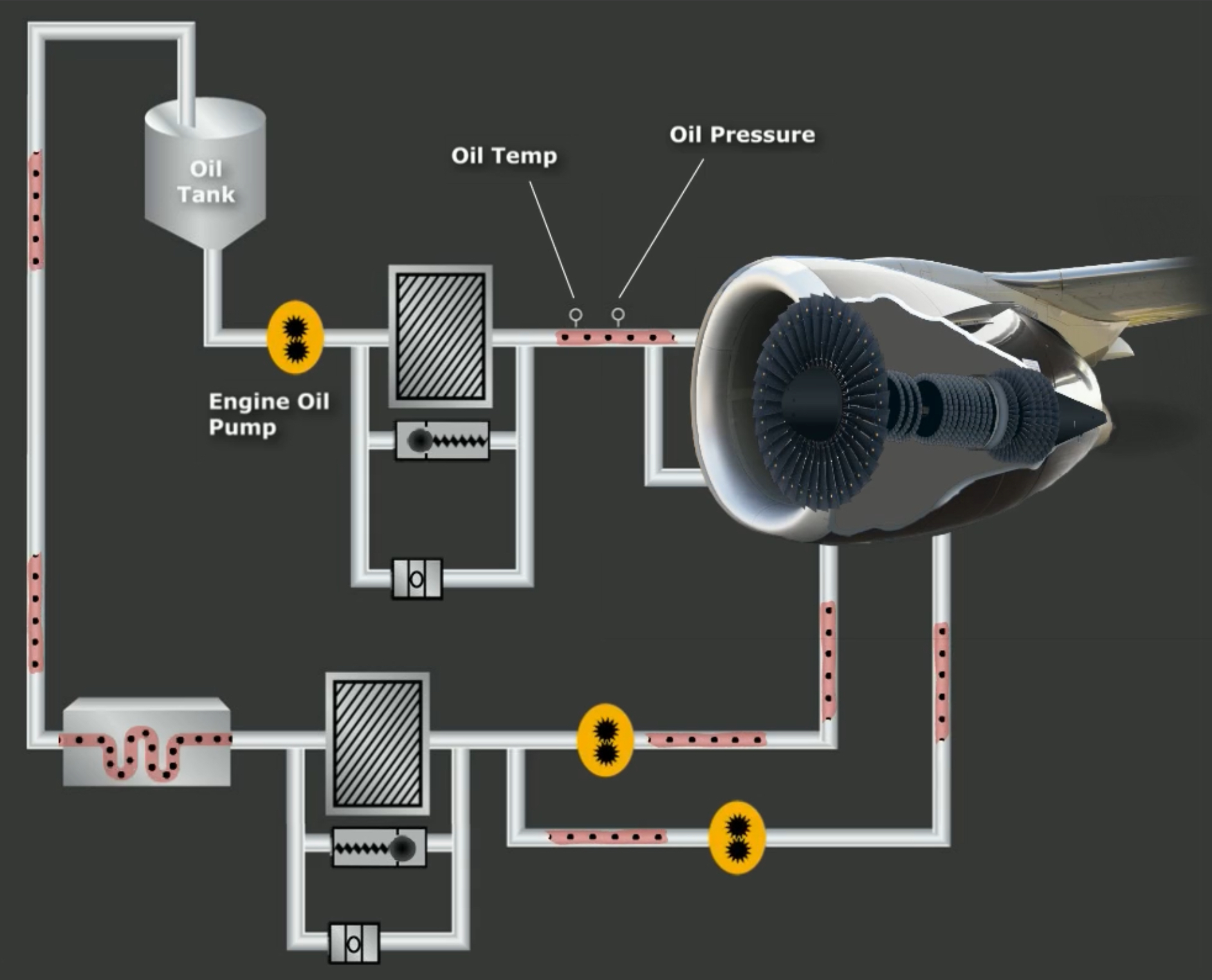
Oil is returned to the tank via scavenge pumps and an oil filter, which can be bypassed with an OIL FILTER BYPASS indication on the DEU.
After the filter, the oil passes through an oil cooler prior to returning to the oil tank. Note that the minimum oil requirements for dispatch is 13 quarts, with 18 quarts required for ETOPS.
Oil pressure as displayed on the DEU can be illuminated yellow or red. Note that if oil pressure is in the yellow band with takeoff thrust set, a takeoff should not be performed.
Engine warm up times
Prior to applying takeoff power, it is important to remember engine warmup times. Before takeoff, the crew must verify an increase in oil temperature.
Engine warmup recommendations are the following:
- Run engines for at least two minutes
- Use thrust normally used for taxi
If possible, after high thrust operation (including reverse thrust), run the engines for at least 3 minutes before shutdown. Note that taxiing is applicable to the 3 min period.
Thrust reversers
Each engine has a hydraulically operated thrust reverser.
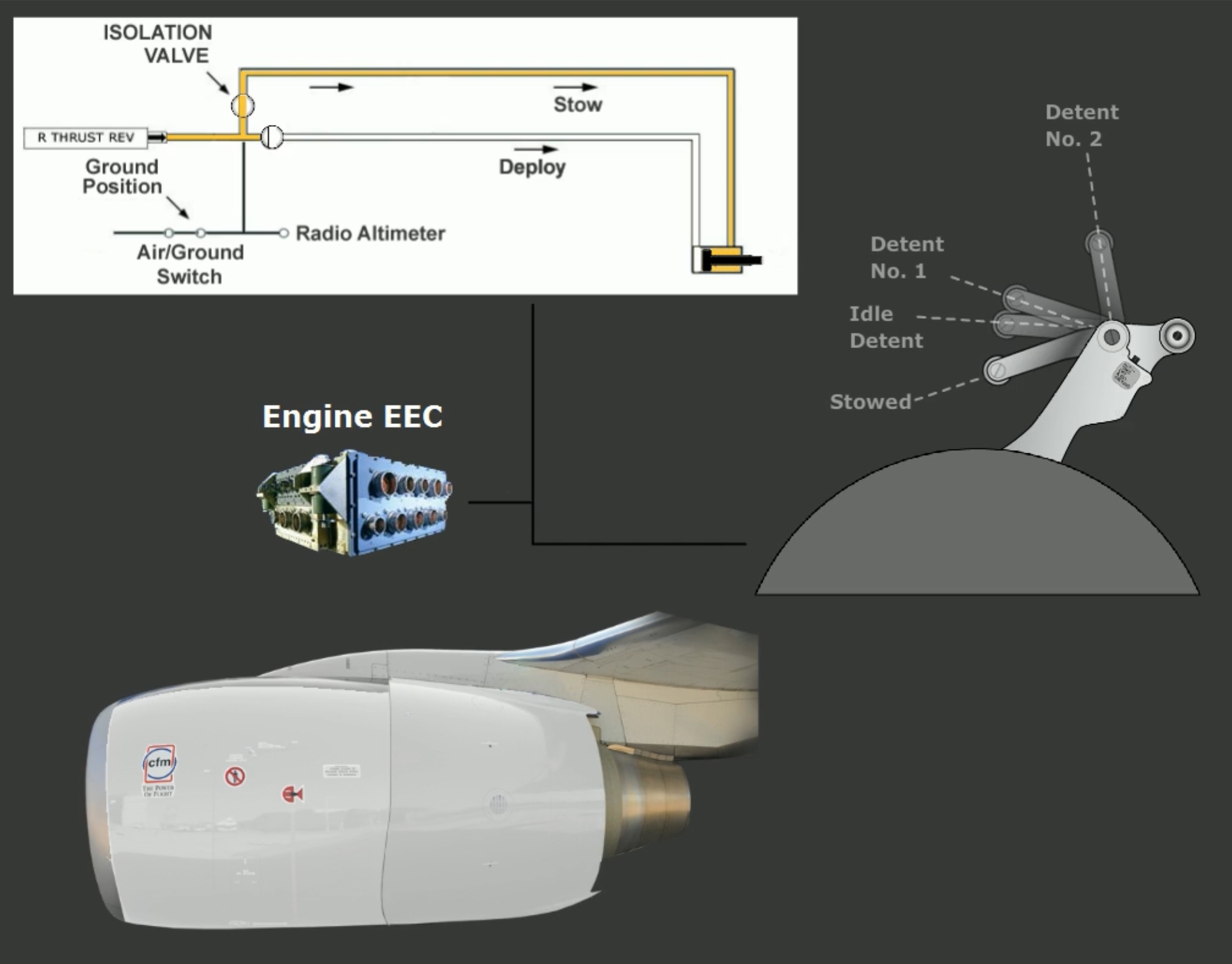
The reverser sleeves move aft and cause the blocker doors to deflect fan discharge forward. The thrust reverse can only be used when either radio altimeter is below 10 ft or PSEU is in ground mode.
Hydraulic pressure for the operation of engine #1 and #2 comes from hydraulic systems A and B, respectively. Should either/both hydraulic systems fail, thrust reverser is available through the standby hydraulic system. When using standby hydraulics, the affected reverser deploys more slowly, leading to some thrust asymmetry.
Whenever reverse thrust is selected, an electro-mechanical lock releases, the isolation valve opens, and the thrust reverser control valve moves to the deploy position.
The REVERSER light on the ENGINE panel illuminates whenever the thrust reverser is commanded to stow. The light should extinguish within 10 seconds when the isolation valve closes. However, anytime the light remains on for more than 12 seconds a malfunction has occurred and the MASTER CAUTION and ENG annunciators will illuminate.
In the event of incomplete stowage or un-commanded movement of the reverser sleeves toward the deployed position, the auto-restow circuit opens the isolation valve and commands the sleeves to stow.
Once the auto-restow circuit is activated, the isolation valve will remain open until: ?
- Thrust reverser is commanded to deploy
- Corrective maintenance action is taken.
How many compressor stages are attached to the N1 rotor?::8 → 4 stage LP Turbine at rear plus 4 stage N1 Fan and LP booster.
How much air bypasses the N1 fan?::About 80%, used for most of engine thrust.
How are the EECs powered?::From dedicated alternators that supply power at >15% N2.
What is soft alternate mode?::EEC uses last valid engine parameters to define engine rating in case of normal signal unavailability.
When is soft alternate mode deactivated?::Soft Alternate remains until the hard alternate mode is entered by retarding thrust lever to idle, or by manually selecting ALTN with the EEC switch.
What is hard alternate mode for the EEC?::Always provides equal or greater than normal thrust for the same thrust lever position.
When do the ENGINE CONTROL lights operate?::On the ground only. They are active up to 80 kts and 30 seconds after landing.
What is Approach Idle mode?::An EEC mode that maintains higher N1 and N2 to improve acceleration in case of a go around. When is Approach Idle mode active?::When flaps are in landing configuration or engine anti-ice is on. If signal faults to EEC, then Approach Idle is active below 15,000 MSL. What does a red framed box around the N1 indication mean on the ground?::That an in-flight exceedance has occurred. What is engine idle N2?::59%. What does a blinking EGT display mean?::EEC sensed an impending hot start.
When does the engine starter automatically close?::At 56% N2. What does the X-BLD indication above N2 mean?::That the aircraft’s speed is too low for a windmilling engine restart. When does the Idle Detent unlock the reverse thrust lever?::When the related thrust reverser is >60% deployed.
When should the reverse thrust lever reduced to idle?::At 60 kts. What happens when you place the Engine Start Valve in IDLE during engine start?::The ignition system is energised through the EEC and both spar and engine fuel valves open. Which igniter must be used when starting with battery power only?::The right igniter, since it is connected to the AC Standby Bus.
What is the engine start process?::When the ENGINE START switch is placed to GRD, the start valve is energized to open with sufficient pneumatic pressure. The starter rotates the N2 compressor, and once it accelerates to 25% and N1 rotation is observed, the Engine Start Lever is moved to IDLE - this cause the spar and engine fuel valves to open, and the EEC provides fuel and ignition.
When should the Engine Start Lever be placed in IDLE during an engine start?::At 25% N2 and observed N1 rotation. What is the maximum engine oil capacity in quarts?::19 quarts. What is the minimum oil quantity for dispatch?::13 quarts, and 18 for ETOPS. How long should the engines be warmed up prior to takeoff?::2 min. How long should engines be cooled down before shutdown after high power operation?::3 min.
Which hydraulic system operates reverse thrust for engine No. 2?::Hydraulic B system
If the EEC normal mode is not available, the EEC downgrades to::The soft alternate mode.
An amber Thrust Reverser (REV) alert indicates::Thrust reverser is moved from stowed position. Placing the ENGINE START switch to FLT provides::Ignition to both igniters. The OIL FILTER BYPASS alert indicates::An impending bypass of the scavenge oil filter. The Engine Start Levers control which valves?::The related engine fuel and spar valves.
During a normal start, when should the ENGINE START switch automatically move from the GRD position to the OFF position?::At 56% N2 RPM.
What does selecting IGN L with the Ignition Select switch provide?::Selects the left igniter for use on both engines.