Pneumatic systems
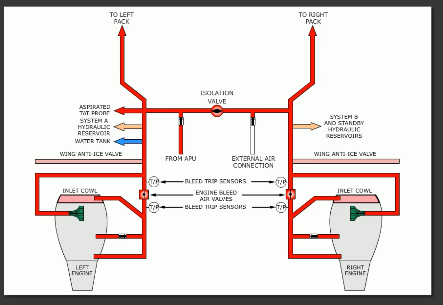
Pneumatic air can be supplied by the engines, the APU, or a HP ground air source. The system is divided into a left and right pneumatic duct.
Normally, the APU or a HP ground air source is used to supply air to the pneumatic system prior to engine start.
The APU introduces bleed air into the left pneumatic duct. Pressurised air from a ground source is supplied to the right duct, and is connected on the right side of the aircraft. Once started, each engine will provide air to its respective duct, although both ducts can be connected through an isolation valve (which is AC 1 operated).
Bleed air pressure and temperature control is fully automatic. There are 4 bleed trip sensors installed to monitor system temperature and pressure.
Pressure is controlled by the engine bleed air valves which act as regulator and shutoff valves.
During flight the engines supply bleed air for the pneumatic system. Air is supplied from the 5th and 9th stages in the engine compressorsection:
- The 5th stage, or Low Pressure air, is the normal bleed air source.
- When 5th stage air is insufficient, the high stage (9th) valve modulates open.
During take-off, climb, and most cruise conditions the 5th bleed is sufficient.
While the engine is not running, the related engine bleed valve remains closed because there is no pressure from the engine. The valve itself is electrically controlled (DC power) via the Engine BLEED Air switch, and pneumatically operated. Additionally, the valve also acts as a PRSOV.
The engine bleed air valve reduces bleed air outflow in response to high bleed air temperature. Should the air or pressure exceed predetermined limits, the BLEED TRIP sensors will go off, illuminating a BLEED TRIP OFF light in the overhead, causing the valve to automatically closed.
The system can be reset by pressing the TRIP RESET switch, which is only possible if temperature is back within limits.
Systems that use pneumatic air
- Engine starting
- Engine Anti-Ice
- Wing Anti-Ice
- Air Conditioning and pressurisation
- Water tank pressurisation
- Aspirated TAT probe (only tails 212 through 228)
- Hydraulic reservoir pressurisation.
- Nitrogen Generation System
Monitoring and controlling
The Bleed Air Panel is used to monitor and control the pneumatic system. Consists of the following:
- DUAL BLEED light
- Duct pressure indicator
- ISO valve switch
- Wing-body overheat lights
- Bleed trip off lights
- Engine bleed switches
- APU bleed switch
- Trip reset switch
The ISOLATION valve remains closed if both engine bleeds are on as well as both air conditioning packs. Should either side bleed or pack be switched off, the isolation valve will automatically open. If all systems return to auto, on, or high, the valve will then close automatically.
Note that the isolation valve is not affected by APU bleed air or HP ground supply.
The above is to ensure sufficient air flows into the cabin, accomplished either by one engine supplying both backs (in the case of an engine bleed fault) or by both engines supplying air to a single pack (in the case of a pack malfunction).
APU
The APU is connected to the pneumatic system through the APU bleed air valve on the left side of the system. Selecting the APU BLEED switch to on will control the valve electrically and operate it open when sufficient pneumatic pressure is available.
The APU can provide bleed air for both packs on the ground, but only one in flight. It is used primarily as a ground pneumatic source for air conditioning pack and engine start.
However, it can be used in the air as a back up in case of engine failure or pneumatic air system malfunction - but only up to 17,000 ft.
After starting the APU the APU GEN OFF BUS light illuminates. This means the APU is available for supplying air, although crews should wait one minute to allow proper warm up time.
It is possible that when the APU bleed valve is opened bac-pressure of the APU can occur, as indicated by the DUAL BLEED light illumination on the overhead. This can happen when:
- The APU bleed air valve is open and the No. 1 engine BLEED Air switch is on, or
- The APU bleed air valve is open, the No. 2 engine BLEED Air switch is on, and the isolation valve is open.
Note that the engines do not have to be started for the DUAL BLEED light to illuminate. The logic only looks at the engine BLEED air switch positions and the position of the APU bleed air valve. It is normal for this light to be on just prior or to or during engine start (?).
To prevent any blowback of pressure into the APU, a check valve is placed in front of the APU duct. However, once the engines are started thrust must not be placed about idle to prevent overpowering the check valve.
Additionally, when both the APU and an engine (generally the left) are started, there is a possibility of back-pressure into the 9th stage bleed duct. This situation cause the 9th stage modulating valve to automatically close.
External high pressure ground connection
The external HP ground connection is located underneath the aircraft, just forward of the right air conditioning vent. When connected, it supplies pneumatic air to the right manifold directly, and to the left as well via the isolation valve.
Ground HP air is primarily used to start the engines should the APU be MEL’d. However, it can also be used to supply pneumatic air to the air conditioning packs.
Should the HP cart be connected, the left engine should be started first due to equipment around the #2 engine. Following a start, the external air should be disconnected and #2 engine started using the Engine Cross-bleed Start procedure.
Warning systems
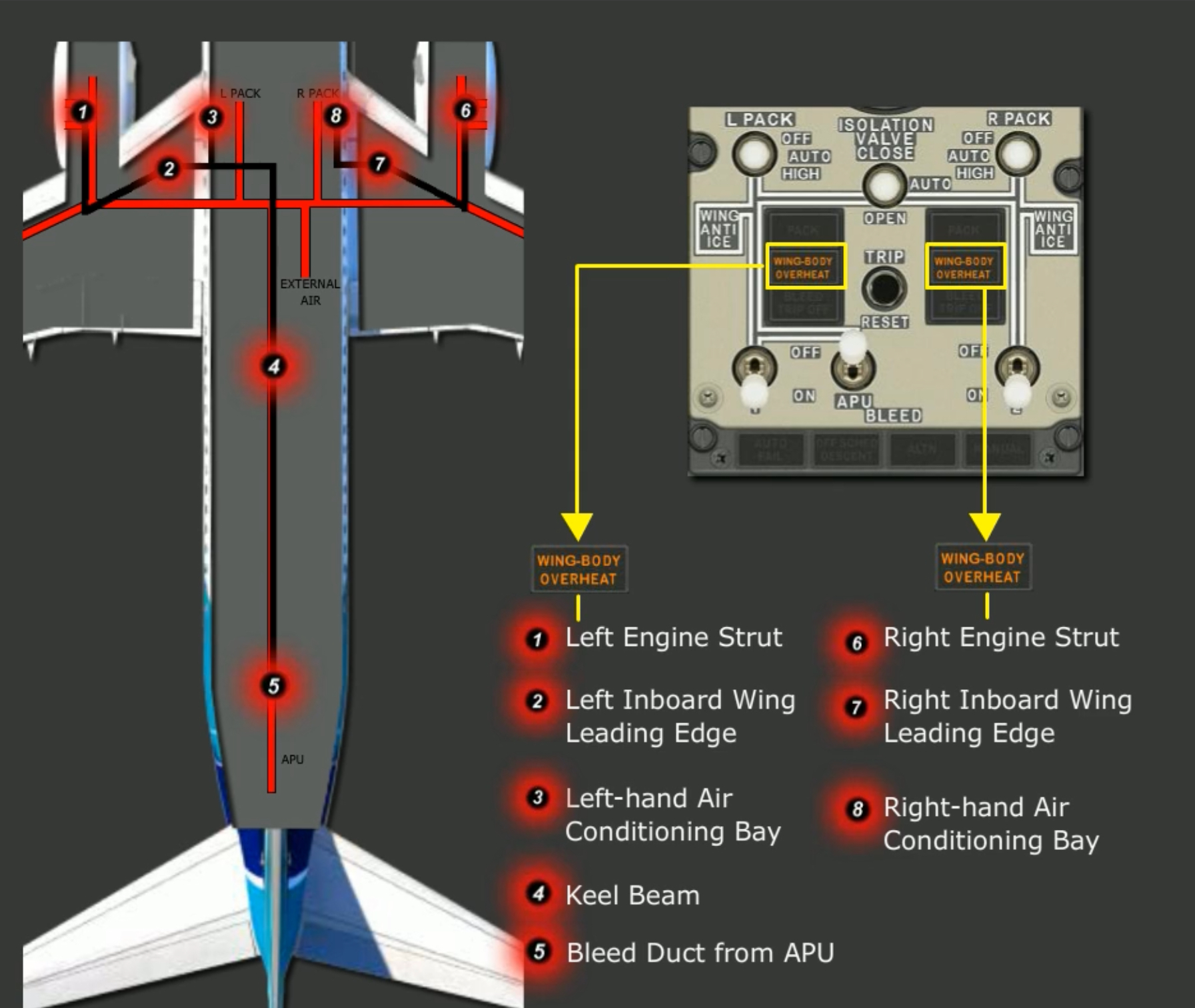
Overheat detectors are installed near the pneumatic ducts to indicate bleed leaks. They sense hot air from duct leaks, which will illuminate a WING-BODY OVERHEAT annunciator.
There are two annunciators. The left annunciator provides detection for:
- left engine strut,
- left inboard leading edge,
- left air conditioning bay,
- keel beam, and
- bleed duct from APU.
The right annunciator provides detection for:
- right engine strut
- right inboard wing leading edge
- right air conditioning bay
The WING-BODY OVERHEAT light also illuminates the AIR CONDITIONING annunciator and the MASTER CAUTION lights. Note that this light cannot be reset by pressing the TRIP RESET switch
Where does the APU supply bleed air?::Into the left pneumatic duct. How is engine bleed air pressure controlled?::By bleed valves that function as pressure regulator and shutoff valves. What are the low and high pressure bleed sources in the engine compressor?::5th stage is LP, 9th is HP. What does the BLEED TRIP OFF light mean?::It means that bleed air pressure or temperature tripped one of the bleed trip sensors, which automatically closes the bleed air valve.
Can the APU provide bleed air for both packs?::Only on the ground, only one of them in flight.
What is the maximum altitude for APU bleed air?::17,000 ft.
When will the DUAL BLEED light illuminate?::When the APU bleed valve is open and either engine bleed air switch is on (in addition to open isolation valve for engine #2). What will cause the 9th stage compressor valve to automatically close after engine start?::Back-pressure from the APU once both are started and the engine bleed valves are open.
What does the WING-BODY OVERHEAT light mean?::That there is a pneumatic leak in the engine strut, inboard wing leading edge, or air conditioning bay. If it is the left side, it may also be the keel beam or bleed duct from APU.
What other lights illuminate along with the WING-BODY OVERHEAT light?::AIR CONDITIONING and MASTER CAUTION. What does the TRIP RESET switch do?::Allows to reset the bleed trip detectors in case of high pneumatic pressure or temperature. It does not work for bleed leaks.
What causes a WING-BODY OVERHEAT light to extinguish?::Cooling of the respective pneumatic duct only. Light cannot be otherwise reset.
What are the sources of bleed air?::Engines, APU, Pressurised external ground air.
Which systems use bleed air?::Engine start, engine and wing anti-ice, air conditioning and pressurisation, water tank pressurisation, hydraulic reservoir pressurisation, aspirated TAT probe. Is it normal to have difference between the left and right pneumatic duct pressure?::Yes, so long there is sufficient air for cabin pressurisation.
Which side of the pneumatic manifold normally receives external ground air?::Right. With the ISOLATION VALVE switch set to AUTO, the valve will open when::Either PACK switch is selected off, or either engine BLEED Air switch is selected off.