Hydraulics
There are 3 independent systems. Two main ones, A and B, and a standby. They supply pressurised hydraulic fluid to operate the following:
- B737 Flight Controls
- Leading edge devices
- Trailing edge flaps
- Landing gear extension and retraction
- Wheel brakes
- Nose wheel steering
- Thrust reversers
- Autopilot
The fluid is contained in reservoirs inside the main gear wheel well.
Controls and indications are located on the overhead, system annunciator, and MFD. The system is monitored via the Hydraulic Control panel.
The standby system is monitored and controlled from the FLT CONTROL panel.
Hydraulic Systems
The hydraulic system is designed so that either the A or the B system can power all flight controls with no decrease in controllability. Both systems have an EDP and an EMDP and Note and maintain a minimum hydraulic pressure of 2,800 psi, to a maximum of 3,500 psi.
EDP
Engine-driven pump.
Produces 3,000 psi and is used to operate the hydraulic system components. These pumps are the primary produces of hydraulic fluid volume, since they can can supply six times more volume than the electric motor-driven pump - this means the EDP can move components on the hydraulic system at a faster rate than the EMDP.
When the pumps are selected
OFFon the overhead panel, the corresponding blocking valve is energised. This means that the pump will continue to operate, but fluid will be blocked from moving on the pump supply line.The pump itself is cooled by hydraulic fluid flowing through the pump. This remains true even when the blocking valve is energised, as fluid will move through the pump and back to the reservoir.
Used along with the EMDP to pressurise hydraulic fluid up to 3,000 psi.
Link to original
The standby hydraulic system is driven by a single EMDP.
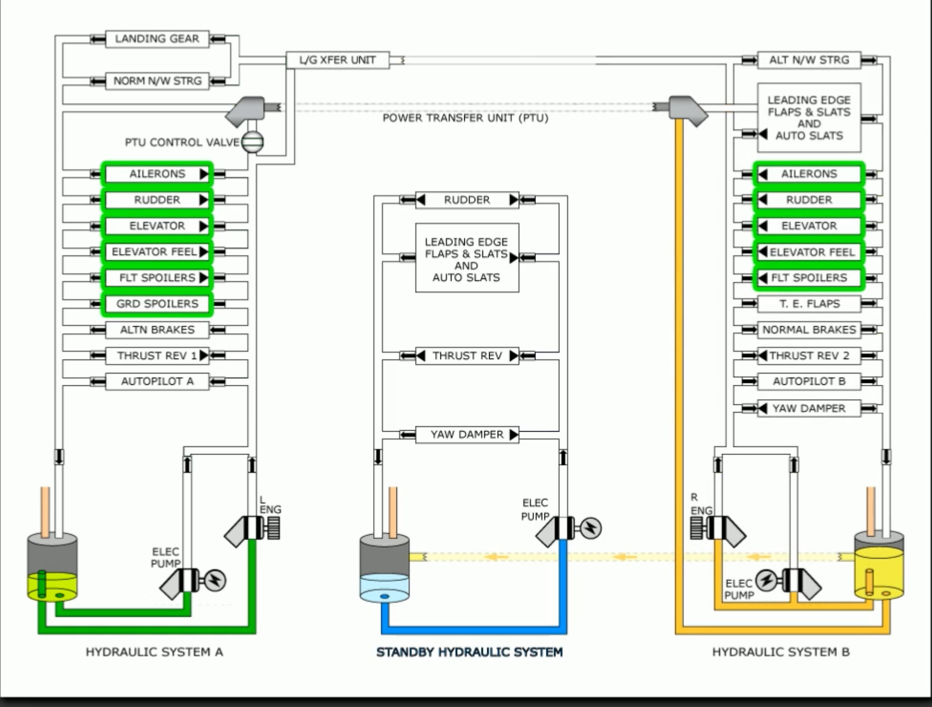
Hydraulic System A
Fluid for this system is taken from a reservoir and pressurised by two hydraulic pumps:
During normal operations, both pumps operate continuously. In particular, the following operate with Hydraulic System A pressure:
- Normal nose wheel steering
- Landing gear
- Ailerons
- Rudder
- Elevator
- Elevator feel
- Flight spoilers (2 on each wing)
- Ground spoilers
- Alternate brakes
- #1 thrust reverser
- Autopilot A
- Power Transfer Unit
The heat exchanger for System A is located in main fuel tank #1.
Hydraulic System B
Fluid for this system is taken from a reservoir and pressurised by two hydraulic pumps: 2) #2 engine EDP 3) EMDP driven by AC Transfer Bus 1
During normal operations, both pumps operate continuously. In particular, the following operate with Hydraulic System B pressure:
- Landing Gear Transfer Unit
- Alternate nose wheel steering
- Leading edge flaps/slats
- Autoslats
- Ailerons
- Rudder
- Elevator
- Elevator feel
- Flight spoilers (2/wing)
- Trailing edge flaps
- Normal brakes
- #2 thrust reverser
- Autopilot B
- Yaw damper
The heat exchanger for system B is located in main fuel tank #2.
Standby Hydraulic System
The standby hydraulic system provides backup in the event that either or both main hydraulic systems fail. It can be activated automatically or manually.
To manually activate the standby pump, either the FLT CONTROL switch can be set to STBY RUD and/or the ALTERNATE FLAPS Master switch can be set to ARM.
Automatic mode is initiated when all of the following apply:
- Loss of system A or B
- Flaps extended
- In flight or wheel speed 60 kts+
FLT CONTROLswitch A or B system ON
The pump will also operate when the main rudder PCU Force Fight Monitor trips.
When activated, the standby rudder shutoff valve opens and allows the standby pump to control the rudder and thrust reversers. When activated, a single EMDP provides power to:
- Rudder
- Leading edge flaps/slats extension
- Thrust reversers
- Standby yaw damper
Additionally, the STBY RUD ON, Master Caution, and FLT CONT lights illuminate.
Hydraulic Reservoirs
| System | Capacity |
|---|---|
| A | 25.7 litres / 6.8 gallons |
| B | 40.5 litres / 10.7 gallons |
| Standby | 13.6 litres / 3.6 gallons |
There are three separate reservoirs, under pressure by the pneumatic air system, that supply fluid to their respective hydraulic pumps/systems. (Note: standby hydraulic system is not directly pressurised; rather, it is pressurised by pressure from system B). Pressurisation provides:
- Positive supply of fluid to pumps
- Normal return pressure in hydraulic system
- Prevents hydraulic fluid from foaming
All 3 reservoirs are located on the forward side of the main wheel well. Fluid passes through a heat exchanger with the fuel system before returning to the reservoir.
The reservoir quantities are displayed on the lower DU by pressing the MFD SYS switch. These are displayed as a percentage, and the information is also shown on gauges in the wheel well.
While on the ground, if fluid level inside either A or B reservoir drops below 76% a white RF, or refill, annunciator is shown next to the hydraulic quantity. This is only valid on the ground with both engines shutdown or after landing with flaps retracted.
Since the standby system is filled through system B, there is no specific quantity indication for it. However, a LOW QUANTITY annunciator may illuminate to indicate the standby system is below 50%.
Reservoir leaks
The system A reservoir is designed with a standpipe extended off the EDP supply line. Should a leak develop in the pump or its related lines the standpipe should prevent a total system loss. Instead, the fluid will drop to the top of the standpipe and indicate approx. 20% full. Pressure is then maintained by the EMDP.
However, there is not standpipe protection for leaks formed in the EMDP supply line. In this scenario, quantity will steadily decrease to zero, and all system pressure will be lost.
Hydraulic system B is designed differently. There is a single standpipe that supplies fluid to both EMDP and EDP. Should a leak occur in any system B component, pressure will be lost and quantity indications will read zero, despite some fluid remaining below the standpipe.
The purpose of this standpipe is to preserve sufficient hydraulic fluid for Power Transfer Operation.
If a leak occurs in the standby reservoir, the quantity will simply decrease to zero. The LOW QUANTITY light will illuminate below 50% capacity, and reservoir B will decrease in quantity to 72% or so.
Hydraulic Pumps
EDP
Engine-driven pump.
Produces 3,000 psi and is used to operate the hydraulic system components. These pumps are the primary produces of hydraulic fluid volume, since they can can supply six times more volume than the electric motor-driven pump - this means the EDP can move components on the hydraulic system at a faster rate than the EMDP.
When the pumps are selected
OFFon the overhead panel, the corresponding blocking valve is energised. This means that the pump will continue to operate, but fluid will be blocked from moving on the pump supply line.The pump itself is cooled by hydraulic fluid flowing through the pump. This remains true even when the blocking valve is energised, as fluid will move through the pump and back to the reservoir.
Used along with the EMDP to pressurise hydraulic fluid up to 3,000 psi.
Link to original
EMDP
Electric motor-driven pump.
Both hydraulic systems A and B also have an associated electric motor-driven pump. These produce hydraulic fluid pressure of 3,000 psi.
The power source for the System A pump is AC Transfer Bus 2, while the source for the System B pump is AC Transfer Bus 1.
Both pumps use fluid for cooling and lubrication. The heat exchangers for systems A and B are located in main fuel tanks #1 and #2 respectively. Because fuel is required to cool the fluid, a minimum amount of 1,675 lbs of fuel in the related fuel tank is required.
Although the EDMPs will automatically shut off when they sense a high temperature, the EDMP switch must be manually shut off as part of the non-normal checklist.
Link to original
Auxiliary Systems
Landing Gear Transfer Unit
During a #1 engine failure, pressure from the EDP is lost. Although the EMDP is still available, it produces a lower volume of hydraulic fluid. Thus, the Landing Gear Transfer unit is placed to help raise the gear on take-off at a normal rate using system B hydraulic pressure. Note that the transfer unit only assists with gear retraction.
The landing transfer unit operates automatically when: ?
- Aircraft is in flight
- #1 engine is considered failed (N2 <50%)
- Landing gear lever is up, and
- Either main landing gear is not up and locked
Power Transfer Unit
The PTU is a hydraulic motor-driven hydraulic pump designed to assist with leading edge device movement on takeoff. It uses fluid pressure from System A to pressurise System B should the right engine driven pump be lost of takeoff
The PTU only pressurises: ?
- Leading edge flaps
- Slats
- Autoslats
The PTU operates automatically when: ?
- System B engine driven pump fails
- Aircraft in flight, and
- Flaps <15, but no up (on later -800s series aircraft this is simplified no “flaps are not up”)
What is the minimum and maximum hydraulic pressure that the EDP/EMDP provide?::They pressurise to 3,000 psi. Minimum is 2,800 psi, maximum is 3,500 psi.
What pumps drive the standby hydraulic system?::A single EMDP.
What causes the standby hydraulic system to automatically activate?::All of: Loss of either or both main hydraulic systems, flaps extended, in flight (or wheel speed 60+), FLT CONTROL switch A or B ON.
What are the hydraulic system reservoir capacities for system A, B, and standby?::6.8 gallons, 10.7 gallons, 3.6 gallons.
When will the RF message appear next to the hydraulic quantity indicators?::When fluid is below 76%.
How is the standby hydraulic system filled?::Through the system B reservoir.
Can you know whether the standby hydraulic reservoir is below 50%?:: Yes, because that’s when the LOW QUANTITY light illuminates.
What do the standpipes in hydraulic systems A and B do?::A system: maintains 20% fluid for EMDP operation in case of leak in EDP system. B System: both pumps lose all fluid, but an amount remains for use in Power Transfer Unit operation.
If there’s a standby hydralic system leak, at what quantity will the other systems stabilise?::System A will be at 100%, since it is unrelated to the standby system. System B will stabilise at about 725.
What is the minimum amount of fuel required to operate the EMDPs?::1,675 lbs in the associated main tank.
The landing gear is powered by Hydraulic System ___ .::A.
Trailing edge flaps are normally powered by Hydraulic System ___ .::B.
The standby system provides backup hydraulic pressure to::Rudder, standby yaw damp, thrust reversers, extension of leading edge flaps & slats.