Electrical System
The electrical system can be divided into three main categories:
The electrical system also contains two batteries used to provide initial power to the aircraft. Note that late model -800 series aircraft have only one factory installed battery. On the ground, external power can also be connected, while the APU can provide power on the ground and in the air, and each engine has one electrical generator mounted on the accessory drive.
The system is controlled via the forward overhead panel.
AC Power System
The AC power system is connected to:
- Engine generators
- APU generator
- GPU
- Transformer Rectifiers (AC input)
The 737NG has two basic operating principles for the AC electrical system:
- No paralleling of AC sources of power
- The source of power being connected to a transfer bus automatically disconnects the existing source of power.
AC Power Sources
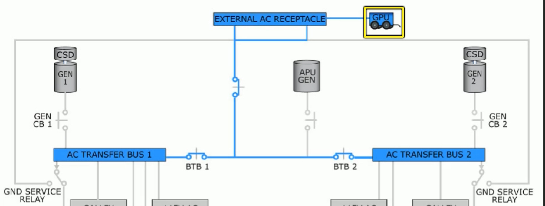
Ground Power Unit
On the ground, electrical power can be supplied by an external source to allow the APU and engines to remain off. The GPU provides 115v AC electrical power to both AC Transfer Busses through bus tie breakers (BTB).
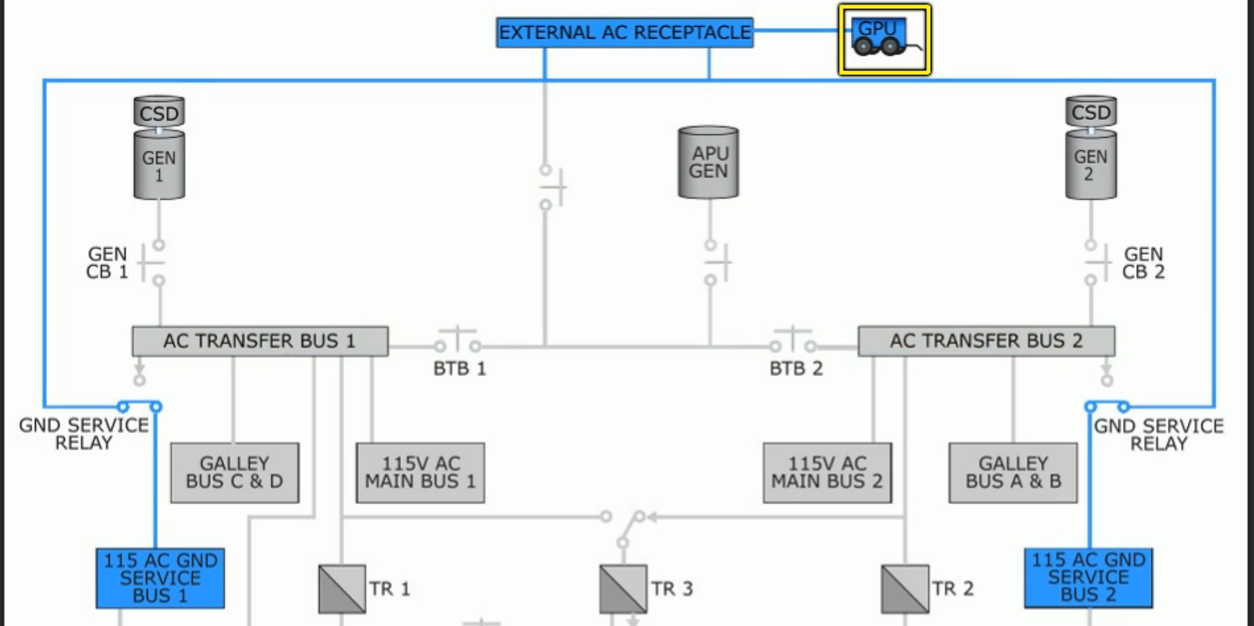
Additionally, the GPU can also provide power directly to the Ground Service Busses via the ground service relay.
Link to original
APU Electrical load
The APU can meet all electrical power demands during ground operations and it can act as an additional power source in-flight. This is done by the single generator in the APU driven by the accessory drive gearbox.
Electrical power from the APU is distributed to the AC Transfer Busses through bus tie breakers. When it’s running but not powering any busses, the
APU GEN BUS OFFlight is illuminated.Control of the APU electrical system is done via the APU generator switches, on the Bus Switching Panel:
If neither AC Transfer Bus is powered by an IDG, moving the APU GEN switch to ON: ?
- Connects both AC Transfer Buses to the APU
- Disconnects external power
If both AC Transfer Busses are powered by an IDG, moving the APU GEN switch to ON: ?
- Connects that side’s AC Transfer Bus to the APU (and disconnects it from the IDG)
- Other AC Transfer Bus continues to receive power from the IDG.
Additionally, should an engine failure occur, the APU can provide power to one AC Transfer Bus while an engine generator provides power to the other AC Transfer Bus.
Link to original
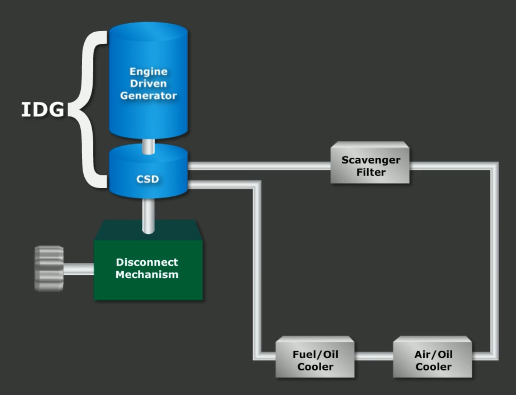
Integrated Drive Generator
While in flight, engine driven generators provide the normal source of AC electrical power. Each engine has one integrated drive generator attached to the accessory case.
Each IDG is comprised of two sections:
- Constant Speed Drive
- Generator
The IDG internal oil system is used not only in the CSD, but also for cooling and lubricating the IDG itself. The oil is routed to an air/oil heat exchanger located in the fan section of the engine before entering the IDG Oil Cooler where it uses fuel to decrease temperature.
Should the temperature of the oil exceed a predetermined limit, the IDG will disconnect automatically. Alternatively, the IDG can be disconnected manually.
Note that the engine must be operating to disconnect an IDG. Additionally, electrical power must be applied to the aircraft and the respective engine start lever must be in IDLE.
Once disconnected, it is not possible to reconnect the IDG in flight; it must be accomplished on the ground by maintenance personnel.
The
DRIVElight on the IDG panel indicates: ?
- IDG low oil pressure, or
- Under frequency condition
The
DRIVElight will illuminate from low oil pressure caused by any of:
- IDG Failure
- Engine shutdown
- IDG auto disconnect due high oil temp
- IDG disconnected via
DISCONNECTswitch.Link to original
Engine Generators
Each engine produces 115V 400 hz power.
Generators are connected via the AC Transfer busses.
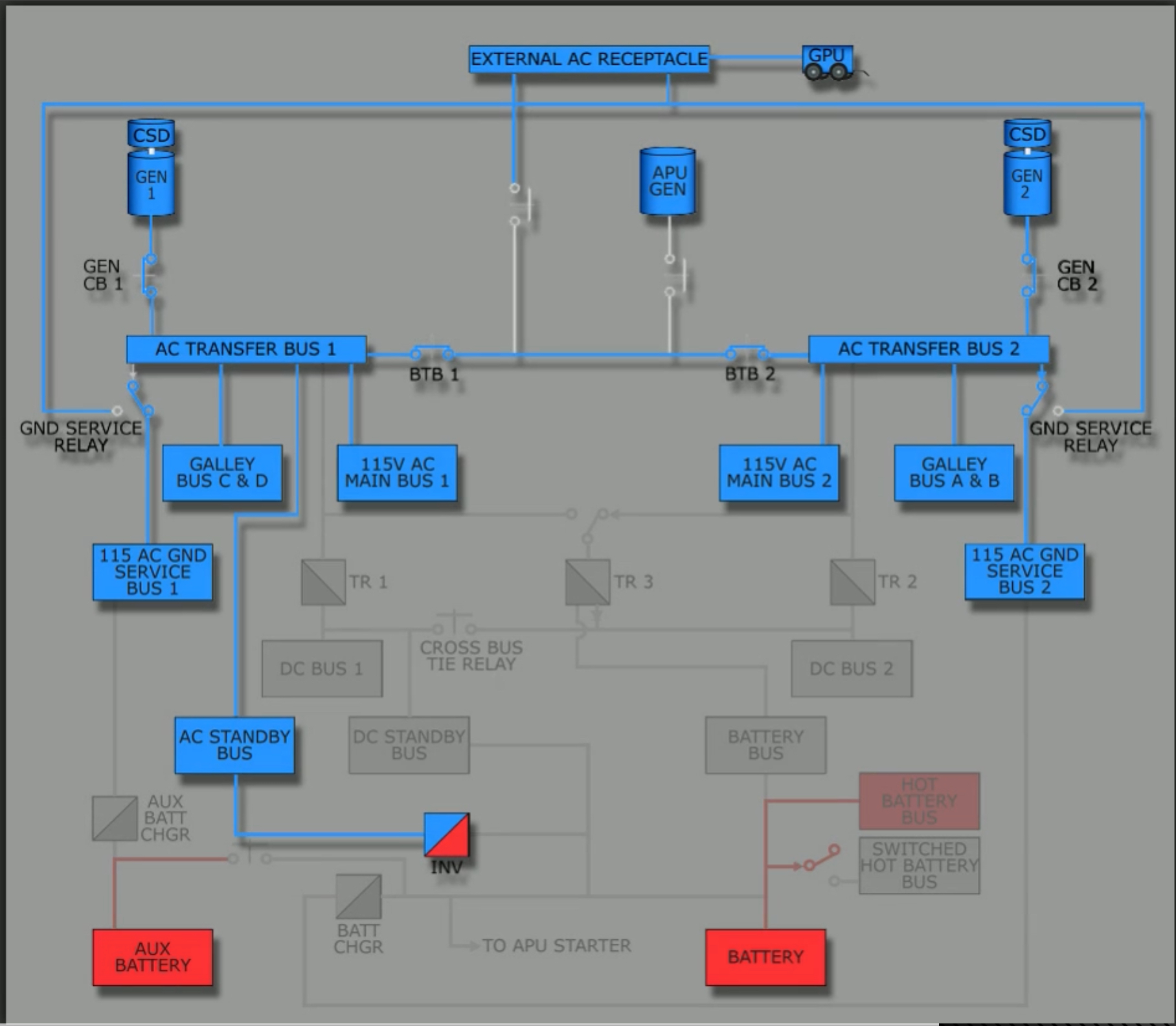
AC Power Distribution
AC Transfer Busses and Bus Transfer
The APU, GPU, and engine generators all supply power to two AC Transfer Buses. Each of those buses is connected to an associated Main Bus, Galley Bus, and Ground Service Bus.
Power distribution:
- AC Transfer Bus
- Main Bus
- Galley Bus
- Ground Service Bus
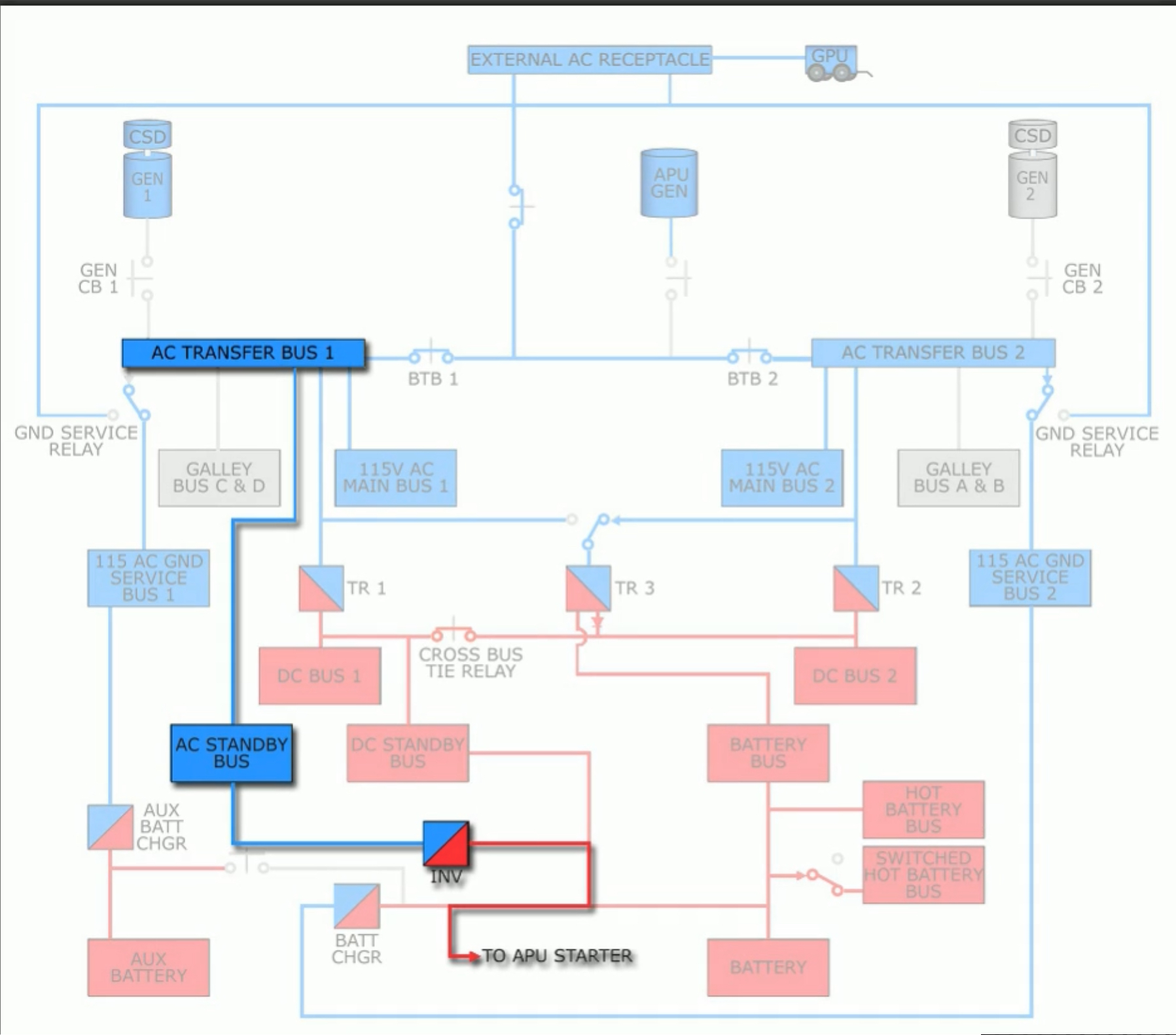
- AC Standby Bus (only from AC Transfer Bus #1)
The system is then divided into two main sides: left side, or Transfer Bus 1, and right side, or Transfer Bus 2. Should any specific AC power source powering either transfer bus fail, the Transfer Bus can be automatically powered by any available power source via the two BTBs.
Bus Tie Breakers
BTBs are automatic switches and open or close depending on the aircraft’s power configuration. They are controlled by the
BUS TRANSswitch located on the overhead.With the switches in
Link to originalAUTO, should a source powering the relevant AC Transfer Bus fail, the source powering the opposite transfer bus automatically picks up the unpowered bus.
When transferring power from the GPU to the APU, only a single APU GEN switch needs to be selected in order to close the APU BTB and open the GPU BTB. Note on the diagram that the APU and GPU cannot power separate busses.
When enabling APU power on, for example, the left APU GEN switch, a SOURCE OFF light will illuminate on the opposite side. The SOURCE OFF light indicates either:
?
- No source has been manually selected, or
- the last manually selected source has been disconnected
After engine starts, the relevant engine generators should be switched on. Once they are both enabled, the BTBs will open, isolating both sides of the electrical system. Should an engine generator fail, however, the BTBs will automatically close to restore all power.
Note: automatic BTB automatic switching can be disabled with the BUS TRANS switch
The aircraft also has logic to prevent electrical failures if a takeoff is performed using the APU as an electrical power source. Should this happen, the BTBs will automatically transfer electrical loads to the engines.
The automatic on-line feature describes the process that maintains electrical power by switching from the APU to the engines automatically, should the APU fail or be shutdown while providing electrical power. This can only happen:
- In flight
- Once per flight
Ground Service Busses
There are two GSBs. They provide power to the aircraft cabin and battery chargers. They can be powered by activating the GROUND SERVICE switch, used to provide cabin lighting, utility outlets, and battery chargers.
The switch is overridden whenever both AC Transfer Busses are powered. The AC Transfer busses are then able to power the GSBs when the GRD PWR switch is selected ON.
Galley Busses
The electrical system contains a CAB/UTIL switch. When ON, the switch allows the galleys and cabin equipment systems to be powered from the AC Transfer busses.
Automatic Load Shedding
The electrical system will automatically shed electrical busses based on actual aircraft load.
Single Engine Generator Operation (buses shed in order):
- Main and Galley busses on Transfer Bus 2
- Main and Galley busses on Transfer Bus 1
- Inflight Entertainment Busses
Whenever power is restored, the busses will be powered again. Manual restoration can be attempted by resetting the CAB/UTIL switch.
APU only operation (buses shed in order:
- All galley and main busses shed
- Both Inflight entertainment busses
On the ground, thge APU tries to carry the entire electrical load. If it can’t, it shed the main and galley busses.
DC Power System
The DC power system includes:
- Batteries
- Transformer Rectifiers (DC output)
Transformer Rectifiers
Used to produce DC power and electrical supply for DC buses. Similar to an inverter.
The aircraft is equipped with 3 TRs. They convert 115v AC power to 28v DC power.
TR 1 receivers power from AC Transfer Bus 1; TR 2 from Transfer Bus 2.
Normally, TR 2 is powered from Transfer Bus 2. However, in the event of a power loss it can receive power from Transfer Bus 1 via the Cross Bus Tie Relay. This switch occurs automatically.
The TRs normally power DC Bus 1 and 2, DC Standby Bus, and the Battery bus. TR 3 is primarily used to supply power to the Battery bus and as a back up for TR 1 and 2.
Any 2 TRs are capable of supplying the total connected load. Note, however, that 2 TRs on opposite sides of the Cross Bus Tie Relay are needed during an ILS upon glideslope capture.
In flight, a TR unit annunciator light indicates:
- TR 1 failed, or
- TR 2 and TR 3 failed
On the ground the light indicates that any TR fault has occurred.
Link to original
DC Busses and Cross Bus Tie Relay
DC Bus 1, 2 and the DC Standby bus are connected via the Cross Bus Tie Relay. During most segments, the relay is closed, connecting the busses. This leads to the normal TR operating condition.
The Cross Bus Tie Relay opens automatically: ?
- At glideslope capture with the flight directors or auto pilot selected to ILS approach, or
BUS TRANSFERswitch set toOFF
This isolates the DC busses and prevents the failure of a single bus from affecting both navigation receivers and flight control computers.
Battery / Battery Buses
The aircraft has two 24v NiCad batteries - main and auxiliary - located in the E&E compartment. Note: Some aircraft are equipped with a single battery.
Both batteries are charged automatically and provide power to the DC system. Normally, the auxiliary battery is isolated from the power distribution system; however, when the main battery is powering the standby system, the auxiliary battery is connected and operates in parallel with the main battery.
The two batteries have sufficient capacity to fully power the standby system for 60 minutes - each battery alone lasting at least 30 minutes.
Battery voltage range is 22 - 30 volts. Should excessive discharge be detected an amber BAT DISCHARGE light will illuminate.
There are five busses connected to the battery: ?
- Battery Bus
- DC Standby Bus
- Hot Battery Bus
- Switched Hot Battery Bus
- AC standby bus
The difference between the Hot Bus and the Switched Hot Bus is that the former is always powered from the battery, while the latter is powered when the BAT switch is selected ON.
The batteries are charged by 115v AC power chargers that convert the power to DC. AC Ground Service Bus 2 provides power for the Main battery, while AC Ground Service Bus 1 provides power for the Auxiliary battery.
These chargers have two modes of operation:
- Charge Mode
- Constant voltage TR mode
The chargers operate in charge mode when the battery voltage drops below a certain limit. Once a battery is fully charged, the chargers switch to constant voltage TR to provide trickle charge into the batteries.
Additionally, the main battery charger in TR mode can power loads connected to the Hot and Switched Hot Bat busses, in addition to power the Battery Bus in the case of TR 3 failure. It is also possible for the main battery charger to power both the AC and DC standby busses in the case of AC Transfer Bus or DC Standby Bus source power failures.
Standby Power System
Standby AC and DC busses
These busses provide sufficient power for operation. They can be powered by multiple sources and are essential to the standby power supply.
Normally, AC Standby Bus receives power from Transfer Bus 1. However, if this power is not available the AC Standby Bus can be powered from the Main Battery via the Static Inverter. When wired such, the AC Standby Bus can remain powered in the event of partial or total generator failures.
Likewise, the DC Standby Bus normally receives power from all three TRs. However, if this power is not available the DC Standby Bus can be powered directly from the batteries - both Main battery and Aux Battery.
The standby power system has the following busses: ?
- Switched Hot Bat Bus
- Hot Bat Bus
- Battery Bus
- DC Standby Bus
- AC Standby Bus
On standby power, only the following instruments, flight management, and navigation systems are available:
- CA’s outboard DU with PFD
- CA’s inboard DU with ND
- Standby instruments
- Left FMC and CDU
- Clocks
- Left EFIS Control Panel
- VHF/NAV #1
- ILS #1
- Left IRS
- Left GPS
- DME #1
- Marker Beacon
- ADF #1
- XPNDR #1
The STANDBY POWER light illuminates whenever any of the following are not powered:
?
- AC Standby Bus
- DC Standby Bus
- Battery Bus
Manually switching the Standby Power switch to OFF removes power from the above busses (if on standby power).
How many batteries does the aircraft have?::Two, a main and an auxiliary.
What type of batteries does the aircraft have?::Two 24v NiCad batteries.
How much time can a single fully charged battery provide for the Standby system?::A minimum of 30 minutes.
What is the basic battery voltage range?::22 - 30 volts.
What is the difference between the Hot Bat Bus and the Switched Hot Bat Bus?::The former is always powered, the latter is powered when the BAT switch is selected ON.
When is the Ram Air Turbine (RAT) deployed?::There is not RAT.
What does the blue GRD POWER AVAILABLE light indicate?::External power is connected and meets aircraft quality standards.
What does the blue APU GEN OFF BUS light indicate?::The APU is running and not powering any AC Transfer Bus.
What causes the DRIVE light to illuminate?::IDG low oil pressure or under frequency condition exists.
IDG low oil pressure, with the DRIVE light illuminated, is caused by::Engine shutdown, IDG failure or manual disconnect, automatic disconnect.
The GEN OFF BUS light only illuminates when the engine generator is running and not powering the related AC Transfer Bus.::False. It illuminates any time the generator is not powering the AC Transfer Bus, even when the engine is shut down.
What is the purpose of the Bus Tie Breakers?::Automatically control AC power distribution.
What is the purpose of selecting the BUS TRANSFER switch OFF?::To open the cross bus tie relay and inhibit Bus Tie Breaker auto switching.
What is the purpose of the automatic on-line feature?::To automatically transfer power to engine generators in the event the APU fails or is shutdown while connected to both AC Transfer Busses.
Automatic on-line feature operates only in flight and only once per flight.::True.
What does the TRANSFER BUS OFF light indicate?::The respective AC Transfer Bus is not powered.
The Ground Service Busses provide power to::Aircraft cabin and battery chargers.
How many Transformer Rectifiers are installed?::3.
How many TR units are capable of supplying total connected load during an ILS approach upon glideslope capture with APP mode selected?::2.
What is the normal AC source of power for TR3?::AC Transfer Bus 2 with auto backup from AC Transfer Bus 1.
A TR UNIT light in-flight indicates::TR1 or (TR2 and TR3) have failed.
A TR UNIT light on the ground indicates::That any TR has failed.
What is the aircraft power source while operating on standby power?::Batteries, main and aux (if installed).
During flight, an ELEC light indicates a fault in the DC power system or standby system.::False.
What happens with the STANDBY POWER switch is placed to the BAT position?::AC Standby, DC Standby, and Battery busses are placed on battery power.