Warning Systems
- EGPWS
- TCAS
- Operational Warning Systems
- Master Caution System
- Stall Warnings
- Takeoff Configuration Warning
- Altitude Alerting System
- Proximity Switch Electronic Unit
- Predictive Windshear
- Landing Gear
GPWS
GPWS provides warnings for flighit close to terrain, obstacles, and through windshear.
GPWS uses:
- rad alt,
- configuration,
- glideslope,
- airspeed
- altitude.
EGPWS also incorporates a database of all man made obstacles. In addition to the traditional GPWS warnings, EGPWS also provides alerts for:
- Large descent rates
- Terrain closure rates
- Altitude loss after t/l go around
- Terrain clearance
Newer GPWS uses GPS positioning for look ahead terrain alerts. It also includes terrain clearance floor protection and terrain awareness.
The system is controlled from the FO’s forward panel. The SYS TEST button momentarily starts a confidence test of the GPWS computer. It also has 3 inhibit switches to turn of certain warnings, such as:
- Flaps (allows for low flap or flapless landings)
- Gear (disables gear-down and lock alerts)
- Terrain (disables look-ahead and terrain display)
GPWS GLIDE SLOPE warnings below 1,000 ft AGLcan be inhibited by pressing the BELOW G/S switch on the forward instrument panel.
Terrain awareness is displayed on the navigation display. Pressing TERR on the EFIS control panel displays terrain.
Some alerts:
- Excessive descent rate
- Based on radio altitude and descent rate
- Begins with “SINK RATE”
- Goes on to “PULL UP”
- Terrain closure rate
- Compares radio altitude and radio altitude closure rate
- Alert is adjusted based on whether flaps are on landing config
- Begins with “TERRAIN”
- Goes on to “PULL UP”
- Altitude Loss After Takeoff
- Below 1,500 ft after take-off
- Dependent on descent rate and radio altitude
- If altitude loss during climb out:
- “Don’t Sink”
- If too low after that:
- “TOO LOW TERRAIN”
- Gear or Flaps not in configuration
- When close to terrain not in landing configuration.
- Gear comes on through 500 ft without gear ddown
- “TOO LOW - GEAR”
- Landing flaps are considered 30 degrees or greater ^86dd27
- “TOO LOW - FLAPS”
- Glideslope deviation:
- Below 1,000 ft AGL
- IF deviations below 1.3 dots:
- “GLIDESLOPE”
- If below 2 dots
- Same as above but louder and more frequent.
- Advisory alerts:
- Bank angle
- 35 degrees, 40 degrees, 45 degrees
- Radio altitude callout
- Approaching Minimums
- Minimums
- Bank angle
GPWS Approach Callouts
These callouts are made to enhance crew awareness on approach. The first two calls, ONE THOUSAND and FIVE HUNDRED are based on barometric altitudes.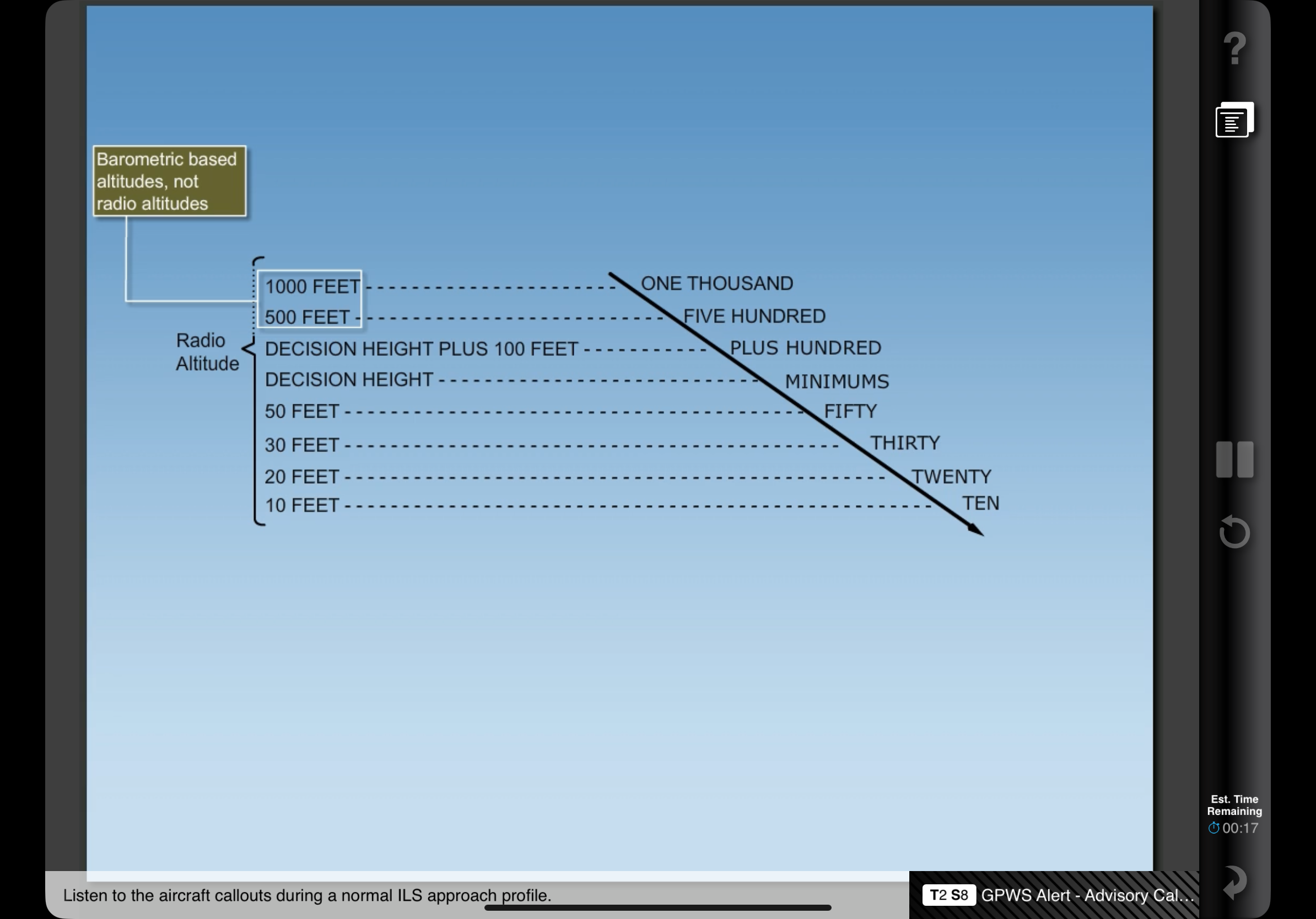
GPWS Windshear
Detects horizontal and vertical windshear below 1,500 radio altitude. Detects changes of airspeed and up/downdrafts to alert windshear.
EGPWS
Compares track position and GPS data.
Makes callouts for terrain within 40 to 60 seconds with a CAUTION, while 20 to 30 seconds from projected impact there is a WARNING.
It also alerts crew for Too Low on approach:
- Uses Terrain Clearance Floor
- 700 ft protection from terrain and obstacles when the aircraft is more than 15 nm from airport.
- Gradually decreases on approach to runway
- Breaking this floor creates a TOO LOW - TERRAIN warning and a PULL UP indication on PFD
- Runway Field Clearance Floor
- Calculates height above runway with geometric altitude.
- Corrects for altimeter errors with:
- Pressure altitude
- GPS altitude
- Radio altitude
- Terrain elevation data
- Runway elevation data
- Rises to 300 ft AGL for 5 miles.
The database contains all worldwide runways 3,500 ft or longer.
Terrain Awareness
Note that terrain and weather cannot be displayed together. Terrain awareness is shown automatically when a look-ahead terrain alert occurs and the terrain display is not selected, and the PFDs are in expanded MAP, center MAP, expanded VOR, or expanded APP modes.
TCAS
Traffic input is provided by two directional antennas on the upper and lower fuselage. TCAS interrogates other transponders and predicts their position.
The distance to alert is dependent on aircraft closure rates.
Only works with other aiorcraft with operating Mode C transponders.
Controlled by transponder panel on centre pedestal. TCAS functions are controlled by the mode selection knob.
Normally, traffic is displayed 2,500 ft above and below aircraft. Traffic is displayed on the MFD, and shown when pressing TFC on the EFIS control panel.
Vertical motion arrows are displayed with climbs or descents of at least 500 FPM.
Other traffic: No threat 6+ miles laterally 1,200 ft vertically Proximate traffic No collision threat Within 6 miles laterally Within 1,200 ft vertically Solid white diamond Traffic advisory When aircraft closure rates become a threat Resolution advisory When traffic separation is at minimum and action must be taken.
TAs are generated approximately 40 seconds prior to the point of closes approach. TAs should led to visual verification of threat.
If the separation decreases, an RA will be generated. This is within 25 seconds of point of closest approach:
Note that only pitch and vertical speed guidance is offered.
- Preventative Action RA
- Occurs when current flight path provides safe separation and a change in flight path may cause separation loss.
- Action: maintain path and do not pitch into red area on Attitude Indicator
- Corrective Action RA
- Requires a maneuver by flight crew.
- The aircraft must be outside TCAS symbol
- May be instructed to:
- Climb
- Descend
- Reduce vertical rate
- May be instructed to:
- Increase Corrective Action
- If a Corrective Action RA is not sufficient, an ICRA will sound.
- Directs crew to increase maneuver rate or reverse flight path
TCAS inhibit modes (in rad alt):
- RAs <1,000 ft
- TCAS voice alerts <500ft
- Increase Descent RAs <1,500 ft
- Descend RAs < 1,100 ft
All GPWS and windshear warnings have priority over TCAS.
Operational Warning Systems
Warnings that alert regarding status and configuration of aircraft. Color coded as follows:
- RED:
- Conditions that require immediate attention
- Includes:
- Fires
- Auto-pilot/Auto-throttle disconnects
- Unsafe landing configurations
- AMBER:
- Conditions that require timely attention
- BLUE:
- Conditions that do not require immediate attention or action
- Includes:
- Equipment status
- Electrical availability
- Valve position
- FA and ground comms call
Master Caution System
There are two Master Caution lights on the glare shield. They illuminate and remain so when a caution condition exists.
When a MASTER CAUTION or MASTER WARNING occurs, the System Annunciator Panel Lights will also illuminate, indicating the specific system where the fault exists. There are 12 systems included on the System Annunciator Panel (note that there are two panels, and each contains 6 different systems).
Pressing the MASTER CAUTION light resets the system and extinguishes the CAUTION and SAPL lights. However, the specific fault indication remains lit.
The system can also recall malfunctions by pressing the System Annunciator Panel: when pressed, any fault previously cancelled re-illuminates.
Airspeed / Stall Warnings
A clacker sound provides aural warnings anytime maximum airspeed is exceeded. The only way to silence it is to slow below Vmo/Mmo.
Can be tested on the overhead panel on the ground by pressing the MACH AIRSPEED WARNING test buttons.
Stall warnings will start with stick shakers, run by motors fitted to each control column. These motors are controlled by two Stall Management Yaw Damper computers.
These computers measure:
- Alpha vane
- ADIRU inputs
- Anti-ice controls
- Wing configuration
- Air/grpund sensing
- Thrust
- FMC options
Takeoff Configuration Warning
Prevents crew from taking off in incorrect configurations. The system is armed while the aircraft is on the ground and the thrust levers are advanced.
Intermittent warning horn sounds if:
- Stabilizer trim is not in t/o range (green band)
- Speed brake lever not down
- Spoiler control valve is open
- Parking brake is set
- Leading edge devices not configured or show uncommanded motion
- Trailing edge flaps are skewed or asymmetrical
- Trailing edge flaps not in take-off range (1 - 25)
Altitude Alerting System
Alerts crew on approach or deviation from MCP selected altitude. It is inhibited when glideslope is captured or flaps are extended to 25 or greater.
A white box appears around the selected altitude display on the PFD 750 ft prior to reaching target altitude. The box disappears 200 ft prior to reaching target altitude.
When deviating 200+ ft from selected altitude, the altitude alert sounds and the altitude box turns to amber and flashes. It will remain so until the deviation is reduced to less than 200 ft or a new altitude is selected.
PSEU
Proximity Switch Electronic Unit
Some of the systems that the PSEU controls are:
- Landing gear position indication and warning
- Take-off warning
- Air/Ground Relays
- Engine Control
- Stall Warning
- Anti-ice
- Cabin pressurisation
The PSEU monitors the following:
- Air/Ground sensing
- Landing gear
- Take/off and landing config warnings
If a PSEU fault is detected or an over wing exit flight lock fails to disengage when commanded the PSEU light and overhead annunciation will illuminate. For other simple faults the same will happen, but only after landing.
The lights will extinguish when parking break is set or both engines are turned off.
PSEU fault light is inhibited:
Link to original
- Thrust levels are advanced to takeoff power
- In Flight
- 30 seconds after landing
Predictive Windshear
This system is separate and different from the EGPWS reactive windshear system.
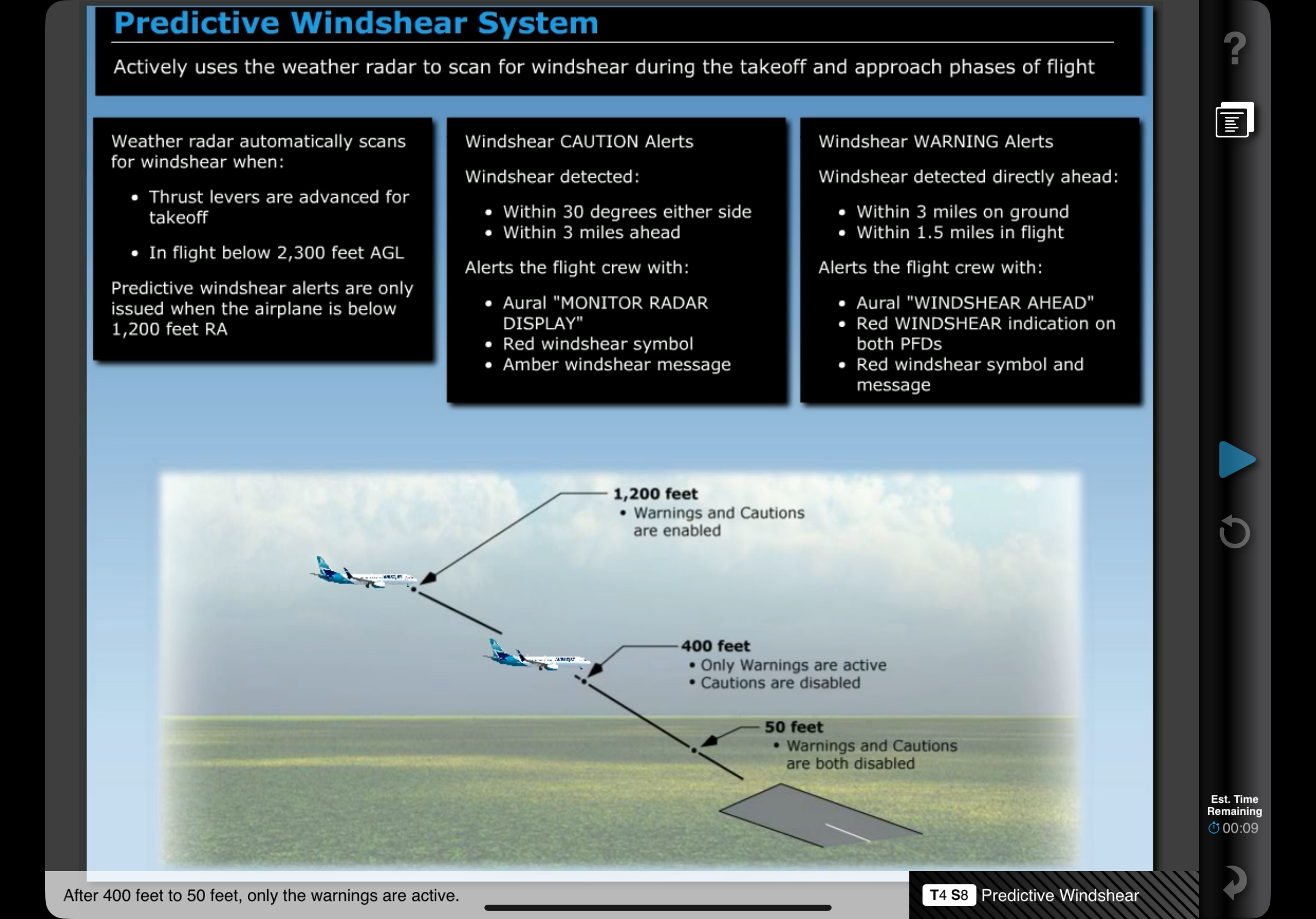
Predictive Windshear uses weather radar to scan for windshear during takeoff and approach phases of flight. The radar detects microburts and windshear events, but it is not able to detect if for non-moisture matter events.
Weather radar scans when:
- AC on ground with thrust on takeoff
- In flight below 2,300 AGL
However, the alerts are only issued when the airplane is below 1,200 radio altitude.
Alerts are only available 12 seconds after weather radar is enabled, due to warmup and initalization sequences.
Alerts can be enabled prior to takeoff by pushing EFIS control panel WXR switch.
There are two categories:
- CAUTION:
- Detected within 3 miles ahead
- Within 30 degrees either side
- Will trigger aural MONITOR RADAR DISPLAY,
- WINDSHEAR symbol
- and an amber windshear warning on the ND
- WARNING:
- Directly ahead
- Within 3 miles on ground
- Will triggle aural WINDSHEAR AHEAD
- Red WINDSHEAR indication on both PFDs
- and red windshear symbol and message
- Within 1.5 miles in flight
- Will trigger aural GO AROUND WINDSHEAR AHEAD
- Red WINDSHEAR indication on both PFDs
- and red windshear symbol and message
On take-off, the cautions are enabled from advancement of thrust levers up to 80 kts, then disabled until the aircraft reaches 400 ft AGL. Only the warnings are active throughout the entire take-off sequence.
All warnings and cautions are disabled climbing through 1,200 ft. On approach, all warnings and cautions are active from 1,200 ft to 400 ft. From 400 ft to 50 ft only warnings are active.
Alerts are prioritised by urgency and crew action requirements. Predictive windshear alerts are inhibited during actual windshear warnings, look-ahead terrain warnings, or radio altitude based alerts.
Landing Gear
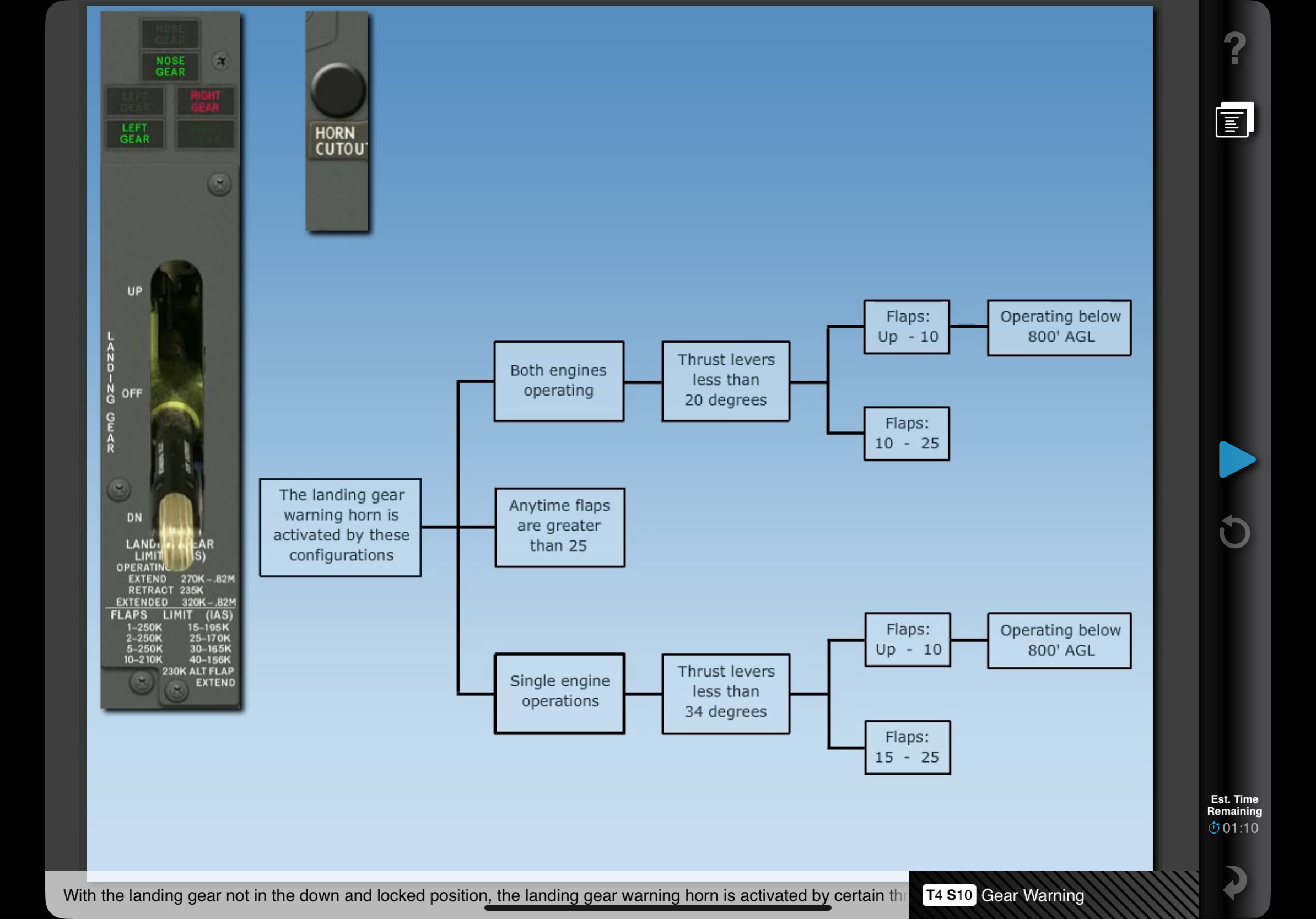
Under some conditions, a steady warning horn sounds when any gear is not down and locked. The horn can be silenced using the Landing Gear Warning Horn Cutout switch (unless flaps are greater than 10 or below 200 ft radio altitude).
If the gear is not in the down and locked position, the landing gear horn is activated by certain conditions:
While descending at a high descent rate on approach in IMC the GPWS alerts “WHOOP WHOOP PULL UP”. What should you do?::Abandon the approach and execute a GPWS escape procedure.
At what altitude will the GPWS alert if the landing hear is not down and locked?::500 ft AGL. A GPWS windshear is a ___ detection system::Reactive. EGPWS uses GPS and a terrain database to “look ahead”::True. Terrain Awareness is displayed on the Navigation Display automatically___::During an EGPWS terrain alert, if not displayed already.
Terrain that is ___ is displayed as amber dots::500 ft below to 2000 ft above the airplane. TCAS can be displayed in which modes?::VOR, Centre MAP, MAP. A TA alert tells you an aircraft is approximately how many seconds from point of closest approach?::40 seconds. An RA alerts the pilot that an aircraft is approximately___ seconds from point of closest approach.::25 seconds. Mach/Airspeed warnings can be cancelled with Master Caution Reset button.::False.
When does the Takeoff Configuration horn sound?::When thrust levers are advanced for takeoff and any of: Stab trim not set, Speed break not down, spoiler control valve open, parking break set, leading edges not configured, trailing edges not configured (1-25) or skewed or asymmetrical.
When is the PSEU light inhibited?::When thrust advanced to takeoff power or 30 seconds after landing.
From take off to what altitude are predictive windshear alerts available?::1,200 ft radio altitude.