Overview
The CDS supply information to the six display units.
They include:
- 2 Primary Flight Displays
- 2 Navigation displays
- Upper Display Unit
- Lower Display Unit
In addition to the displays, following are included as a backup:
- Standby compass
- Integrated Standby Flight Display
Common Display System
The DUs provide flight and engine information to the pilots from the CDS.
The Upper Display Unit displays engine and fuel indications, as well as crew alert messages. The Lower Display Unit operates with the ability to switch between secondary engine parameters and hydraulic system information.
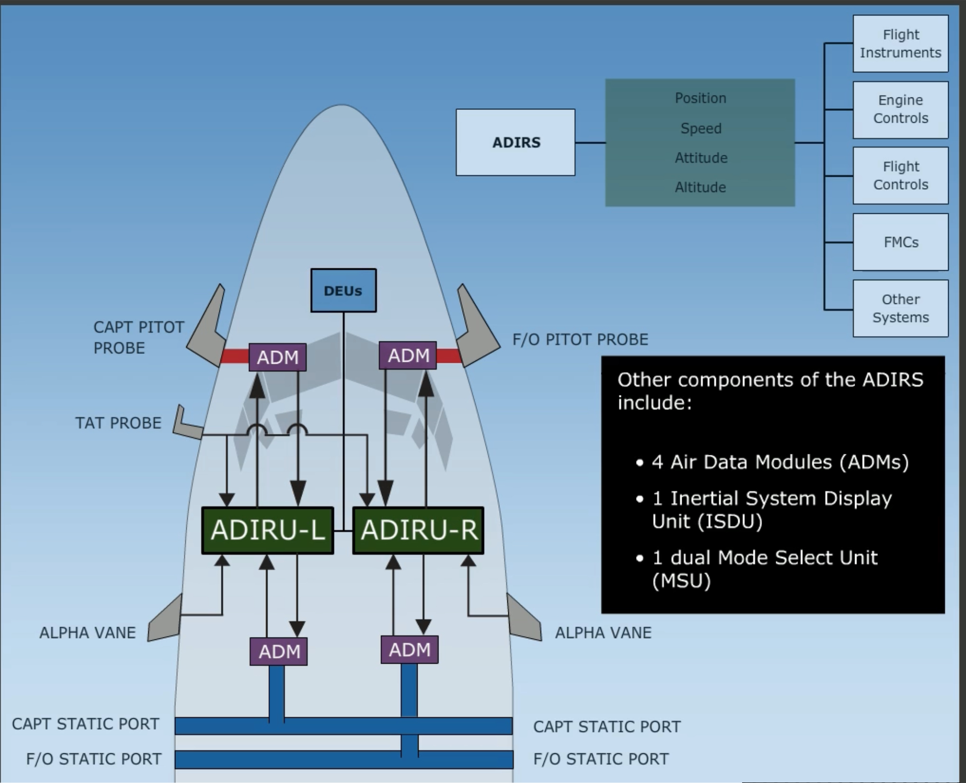
ADIRU
Air Data Inertial Reference Units.
Provides the following information to the instruments, engines, B737 Flight Controls, FMC, and all other systems requiring inertial and air data.:
- Position
- Speed
- Altitude
- Attitude
The system includes two IRUs (Left and Right) which contain internal gyros and accelerometers for position information.
Other components of the ADIRS include:
Two main pitot tubes and four static ports provide pressure information for for speed and altitude. Two Alpha Vanes provide AoA information, and a Total Air Temperature probe provides air temperature to the ADIRS system.
This information is sent to the flight displays by two DEUs.
Link to original
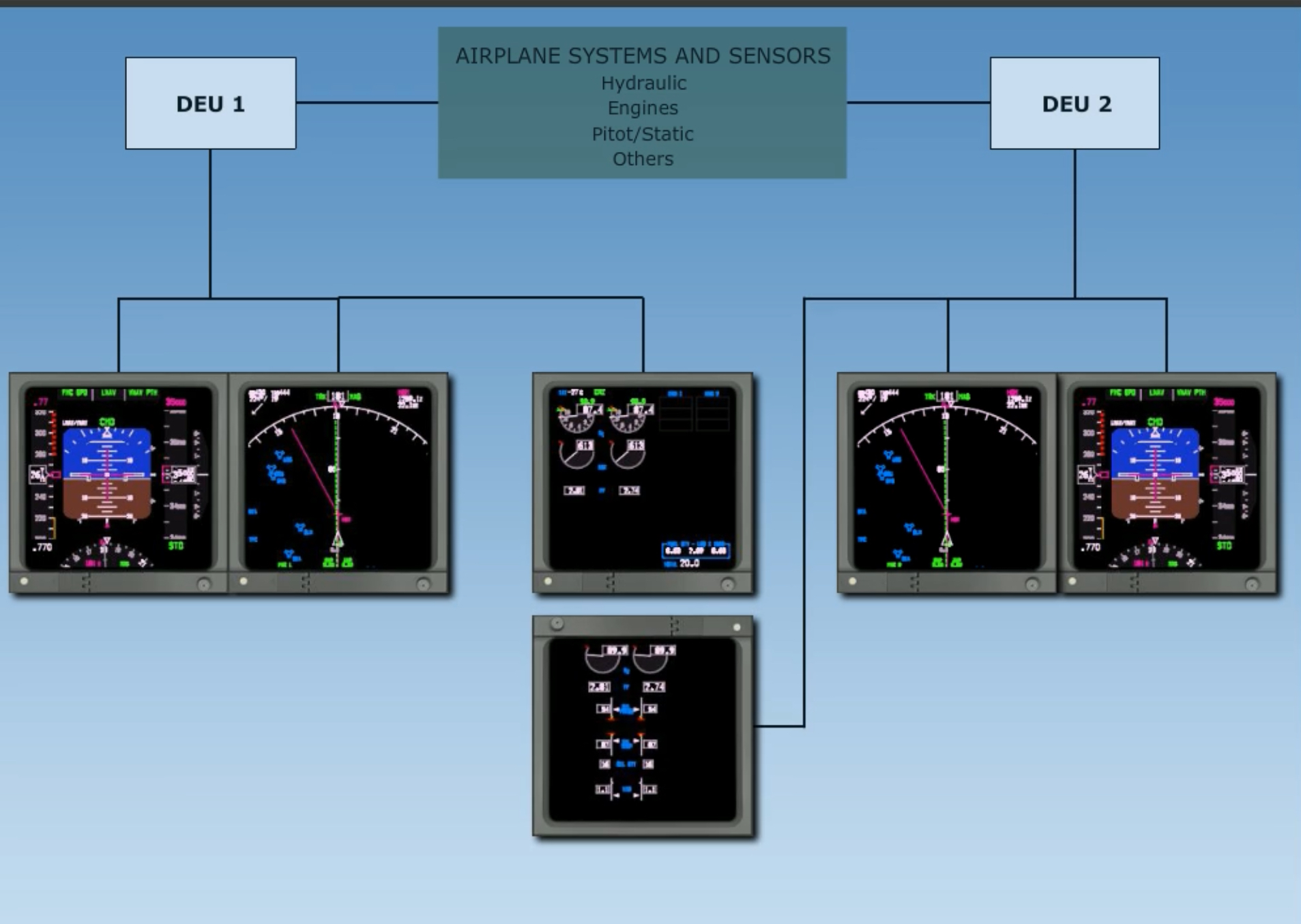
DEU
Display Electronic Unit
The DEUs are computers and distribute information from various aircraft sensors and systems. The data is converted to digital signals and sent to the displays.
During normal operation DEU 1 supplies information to:
While DEU 2 provides information to:
Should either DEU fail, the other DEU will automatically control the other side. It allows all displays to use a single DEU source. *Note that while operating on a single DEU, each pilot still receives information from independent sources and both ADIRUs..
Link to original
EFIS
Electronic Flight Instrument System
With the
Link to originalDISPLAYS CONTROL PANELswitch in theNORMALposition, the left EFIS Control panel operates the captain’s flight instruments, while the right EFIS Control Panel operates the FO’s instruments. Should a panel fail, all displays are controlled by the remaining EFIS Control Panel.
CDS Faults
There are three messages that display when there is a fault in the CDS or DEU system:
| Fault message | Interpretation | Conditions | Color |
|---|---|---|---|
CDS FAULT | Non-dispatchable fault in the CDS system | Ground only prior to second engine start | AMBER |
CDS MAINT | Dispatchable fault in CDS system | Ground only prior to second engine start | WHITE |
DSPLY SOURCE | A DEU has failed after both engines started or airborne | After both engine starts | AMBER |
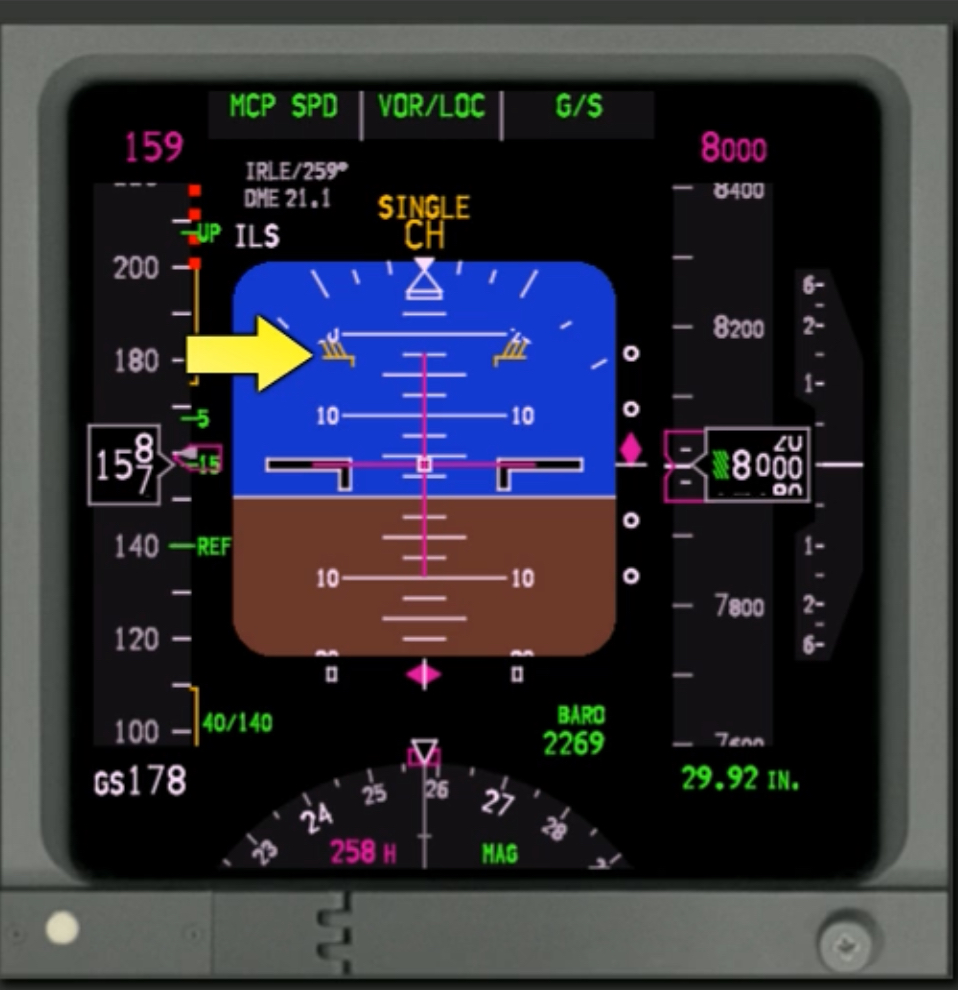
Primary Flight Display
Each pilot’s PFD is normally located on the outboard DU.
Each PFD contains:
- Flight Mode Annunciator
- Autopilot, Flight Director System Status indicator
- ADI
- RADALT
- ILS
- Heading/Track
- ASI/MACH
- Altitude
- VSI
Each PFD displays attitude information from the aircraft’s ADIRU system.
In addition to standard data, the ADIs also provide Pitch Limit Indications that indicate the maximum pitch limit for the current configuration. Going beyond the PLI results in stick shaker activation, and is displayed when the flaps are not up or at slow speeds with the flaps up.
On the speed tape, the maximum speed bar is displayed in red and is adjusted to meet the lowest of:
- Vmo/Mmo with gear and flaps up
- 320 kts when gear down (max gear extended speed)
- Flap limit during each flap extension
The minimum speed bar shows the speed at which the stick shaker will activate, based on gross weight, flap setting, and bank angle.
Additionally, the tape includes a green Speed Trent Vector that computes expected speed within 10 seconds. There are also amber max/min manoeuvring speed indications.
With flaps up, the Maximum Maneuvering Speed indication gives the pilots an additional 0.3g maneuver margin protection to high speed buffet. This may be displayed at high altitude with flaps up and relatively high gross weights.
The minimum speed amber tape displays the flap limit placard speed for the next normal setting, assuming a sequence of 1, 5, 15, and 30.
Control Display Unit
The CDUs are the primary means for interaction between the flight crew and the FMC.
Each CDU page displays up to 6 data lines, along with respective line titles. Line select keys are used to modify the data on any given line; selecting it copies the data into the scratchpad so that they can be modified.
It is also possible to enter data into the scratchpad first and then press a line key to copy the data into that line.
Note that thrust reductions for climb are capped at 25% N1.
CLB-1indicates a 3% thrust reduction (or 10% N1),CLB-2indicates a 6% reduction (or 20% N2).Active CDU data being used by the autoflight system is displayed in magenta.
CDU Conventions
Data entry is accomplished using different methods:
- Via scratchpad with alphanumeric keys
- Transferred to scratchpad from a data line
Data from the scratchpad is transferred to a data line by selecting the adjacent LSK.
Note that the scratchpad must be empty in order to use the LSKs to copy data into it. Additionally, typing characters will overwrite FMC-generated messages on the scratchpad.
Pages containing boxes indicates that data entry into that field is mandatory, such as the
PERF INITpage during preflight since performance calculations are not possible until entries are made into these fields.Dash prompts indicate data that is either:
- Optional
- Used for additional calculation or information
Large fonts displayed on the CDU indicate manually entered information or mandatory altitude restrictions. Small fonts indicate predicted altitude values. Note that only large font altitude data values can be deleted.
When large font values are deleted, they are replaced by a predicted value based on constant angle descents.
Entering altitudes can be done in the
FL200or simply200format. For altitudes below 1,000 ft a leading zero is required.An
Asuffix indicates altitudes to be flow at-or-above.Bsuffixed indicate at-or-below. For restrictions between to altitudes enter lower limit first, then upper limit, i.e.100A120B.Multiple element entries can be placed as a singly entry by separating fields with a slash. For instance, a cruise wind of 100 degrees at 75 kts would be entered via the scratchpad as
100/75.To change single elements in multi-element values requires either a leading or trailing slash, depending on whether the data is on the left or the right of the CDU. To put it simply, include the slash as shown in the data field relative to the entry:
XXX/for items on the inner right side of the scree, while items on the inner left side prepend the slash -/8.0. Data closest to the LSK can be entered without slashes.Elements close to LSK do not requires slashes, while elements further from the LSK require a slash in the appropriate position.
Specific keys
The functions keys give direct access to various CDU pages. An important one is the
EXECkey, which executes any modification that has been entered into the CDU. A pending modification is indicated by a light bar above theEXECkey.
Key Page Includes INIT REFSystem initialisation and performance data menu Position and performance RTERoute pages - page 1 includes origin and destination, as well as company routes Other pages include route segments or direct routings DEP ARRUsed to modify departure and arrival procedures FIXDisplays fix page. Used to display and create fixes on current route LEGSUsed to modify lateral and vertical nav data. Page is called MOD RTEwhen pending modificationIncludes waypoints, speed and altitude at waypoint, RNP/ANP values HOLDHold page. Holding procedures for missed approach are displayed here PROGDynamic flight information data, waypoint and destination, ETA’s, fuel remaining Wind data, RTA (required time of arrival), RNP data Alert Messages
There are 4 alert messages on the sides of each CDU:
- MSG → Message displayed on scratchpad
- OFST → LNAV function is giving lateral offset routing
- CALL → Subsystem other than FMC requests control of CDU
How do you select VREF speeds on the FMC?::On the
Link to originalAPPROACH REFpage, which is accessed with theINIT REFkey during flight. How do you enable pending modifications on the FMC?::If the light bar aboveEXECis on, there is a pending modification. PressEXECto execute said modification. As the aircraft reaches ToC, the FMC/CDU auto sequences from CLB page to CRZ page.::True FPA is the actual flight path angle based on present ground speed and ___ . :: Vertical speed. During a reduced thrust takeoff, the maximum reduction that the FMC will allow is ___ N1.::25% During aCLB-2reduced thrust climb out, N1 is reduced by ___ .::6% Any page containing boxes indicates that data entry into that field is mandatory.::True.