Fuel
Fuel is stored in:
- Two wing tanks
- A centre tank
Each tank contains two AC powered pumps, and they feed fuel directly to the engines and the APU. The system is divided into a left side and a right side, connected by a XFEED valve.
The 737 accepts Jet A and Jet A1 as authorised fuels, although JP-5 and JP-8 can be used as an alternative. However, wide cut fuels, JP-4, or Jet B is prohibited.
Fuel Storage
Fuel capacity on the 737NG is: ?
- 8,630 lbs per wing tank
- 28,803 lbs for centre tank
- Total capacity: 46,063 lbs
The fuel quantity processor calculates total fuel quantity from the independent tank quantities. This information is sent via the DEUs to the FMC and the Fuel Quantity Indicators. With this information, the FMC can also provide several fuel related and advisory messages, such as:
| Message | Translation | Condition |
|---|---|---|
| USING RSV FUEL | Using reserve fuel | Predicted fuel at destination is less than reserves entry on PERF INIT page |
| VERIFY GW AND FUEL | Verify gross weight and fuel | Displayed when fuel data becomes invalid. FMC will use last valid fuel quantity for performance until a manual entry is made |
| INSUFFICIENT FUEL | Insufficient fuel | A change in conditions or flight route results in arrival with <2,000 lbs |
| CHECK FMC FUEL QUANTITY | Check FMC fuel quantity | The FMC detects an unexpected drop in fuel quantity |
Fuel temperature is measured through a sensor in main tank 1, and displayed in degrees C on the fuel control panel. There are some limitations:
- Max fuel temperature → 49 degrees C
- Minimum inflight temperature → +3 degrees of fuel freezing point, or -43 degrees, whichever is higher
Note that there are NO warnings if the fuel approaches this limitation.
Air and fuel vapours flow in and out of the tanks through the fuel vent system. This discharge flows into the surge tanks located at the end of each wing. Should the surge tank be completely full, excess fuel will vent overboard.
The FQIS provides fuel quantity measurements, calculations, and indications. The system is comprised of quantity sensors in each tank, a quantity processor unit, and fuel quantity indicators. Fuel quantity indicators are displayed on the DEU, the fuelling/defuelling panel, and on the CDU.
The system works by measuring fuel volume and density in the tanks. This information is then sent to the fuel quantity processor where the data is turned into a fuel quantity value for each tank.
Fuel measuring sticks are installed on each tank. There are 6 measuring sticks on each wing, and 4 are installed in the centre tank.
There are three fuel alert indications on the upper DEU:
| Fuel Indication | Appears when | Disappears when |
|---|---|---|
| LOW | Fuel quantity <2,000 lbs in either main tank | Quantity >2,500 lbs |
| CONFIG | Centre tank quantity >1,600 lbs, centre pumps at low/no pressure, and either engine running | Centre tank quantity <800 lbs, any centre tank pump high pressure, or both engines shutdown |
| IMBAL | Imbalance of >1,000 lbs between main tanks (inhibited on ground) | Imbalance <200 lbs |
Note that imbalance indications are inhibited on the ground, while fuel LOW indications override IMBAL indications.
Fuel Flow
Fuel is required to be loaded into the main tanks first. Should a specific route require capacity exceeding that of the main tanks, fuel can then be loaded into the centre tank. However, fuel usage is opposite to loading: fuel in the centre tank is used first, and then each main tank feeds its respective engine.
Feed system
The feed system consists of a left and a right engine fuel manifold. Normally, the left main tank pumps and the left centre tank pump pressurise the left manifold. There is a cross-feed valve that allows any tank to feed any engine.
Prior to entering the engine, fuel passes through two oil and fuel liquid to liquid coolers and then two fuel filters. Associated with this process there are two FILTER BYPASS lights that illuminate to indicate an impending filter bypass.
Fuel pumps
Each main tank contains two 115v AC fuel pumps, controlled from the Fuel Control Panel. Any one fuel pump can satisfy engine demand under all thrust conditions.
The centre tank pumps operate much like the main tank pumps, although they provide higher pressure output and they are able to override the pressure of the main tank pumps. A single centre tank fuel pump can satisfy both engine’s demands under all thrust conditions.
The left and right fuel manifolds are separated by the XFEED valve, which is DC motor operated from the battery bus. However, the XFEED valve is not designed to transfer fuel from tank to tank; it can only be supplied from tank to engine.
Should the fuel pumps be inoperative, the engine will continue to operate with fuel supplied through suction feed, although thrust deterioration or flame-out can occur if above FL300.
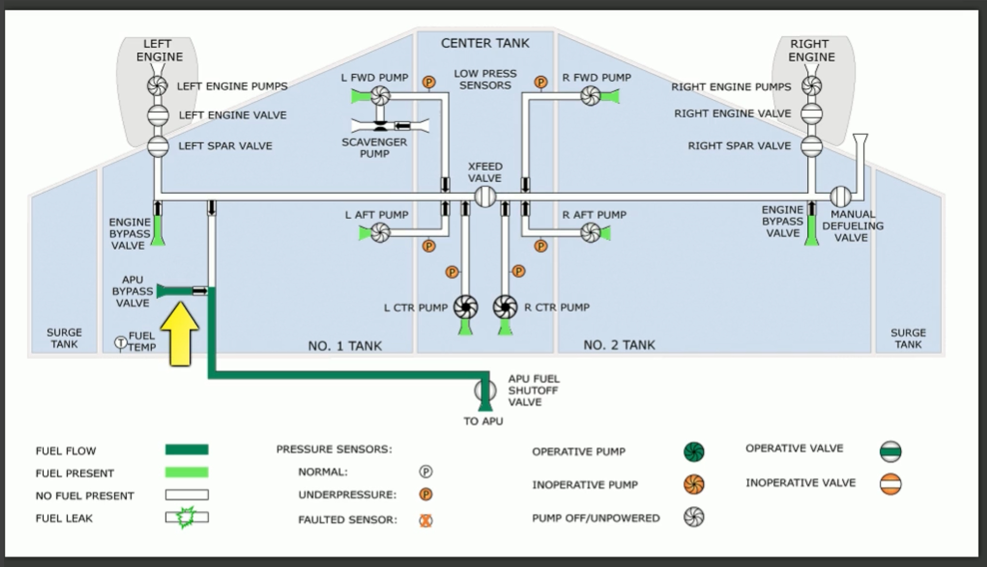
APU
The APU draws its fuel from the left side of the fuel manifold. Either No. 1 main tank fuel pumps can supply fuel to the APU; as well, the APU can suction feed from the left tank. Fuel can be supplied from the right fuel manifold by opening the crossfeed valve.
It is recommended to select the left centre tank pump ON with full main tanks and at least 1,000 lbs in the centre tank to prevent fuel imbalances prior to takeoff.
Fuel Scavenge Pump
A scavenge jet pump is installed in the centre tank. It is designed to scavenge fuel that is inaccessible to the centre tank pumps. It automatically activates when main tank 1 is less than half full. It will continue to operate until all fuel is removed from the centre tank.
Note that the left forward fuel pump must be on to provide motive to the jet pump.
Nitrogen Generation System
A Nitrogen Generation System, or NGS, is installed to convert engine bleed air into nitrogen enriched air. The gas replaces ambient air in the centre tank to reduce the chance of in-tank combustion.
This is a fully automated system that operates continuously after take-off until landing, as long as bleed air pressure is available.
The NGS system is also shutdown when:
- Aircraft is on the ground with NGS not in test mode
- Either engine is not running in flight
- Fire or smoke detection in cargo or main deck areas
- Left air conditioning pack overheat
- Centre tank refueling valve open.
The status of the NGS system is indicated on the main wheel well adjacent to the APU fire control panel.
Fuelling Operations
All normal fuelling operations are accomplished at the fuelling panel, located on the leading edge of the right wing.
Fuel enters the aircraft via a single nozzle; a separate manifold ducts fuel into the three fuel tanks. The fuelling station is automatically powered when the door is opened and either AC power or a battery is turned on.
If no power is available, fuelling can be accomplished by using the Fuel Door Switch Bypass. This supplies power to the fuelling system from the hot battery bus.
There are no flight deck indications that refuelling operations are being conducted.
To defuel or transfer fuel from the aircraft the right fuel manifold must be connected to the defuel valve manifold. These are ground personnel tasks. Main tanks 1 and 2 can be suction defuelled, while any tank can be pressure defuelled.
How many fuel pumps are there?::6 pumps → 2 AC powered pumps per tank. How is total fuel quantity measured?::Sensors in each tank measure volume and density, which is converted into fuel quantity by the fuel processor unit. How many fuel measuring sticks are installed?::16 → 6 on each wing, 4 on centre tank. When does the fuel LOW indication come on?::When fuel is <2,000 lbs in either tank. Disappears once quantity is >2,500 lbs. What does a fuel CONFIG light indicate?::That centre tank quantity is >1,600 lbs but centre tank pumps are producing low/no pressure and an engine is running. When does a fuel CONFIG light disappear?::When centre tank quantity is <800 lbs, a pump is producing high pressure, or both engines are shutdown. What causes the fuel IMBAL light to come on?::Main tank quantities differ by >1,000 lbs. Light stays on until imbalance is <200 lbs. How is fuel temperature measured?::Through a sensor in main tank 1. What is minimum fuel temperature?::3 degrees above fuel freezing point or -43 degrees, whichever is higher. Which pumps pressurise the right engine fuel manifold?::Right main tank pumps and right centre tank pump. Should the fuel FILTER BYPASS light illuminate due to ice in the fuel?::Not normally, since fuel passes through two heaters prior to reaching the filter. How are the fuel pumps powered?::With 115v AV power. Will the engine operate with the fuel pumps off?::Yes, with fuel supplied by suction feed. At what altitude will engine fuel suction feed deteriorate?::FL300. From where does the XFEED fuel valve receive power?::From the battery bus. What is the location and purpose of the fuel scavenger pump?::To scavenge fuel that is inaccessible to the centre pumps. It is located in the left main tank. When does the fuel scavenge pump operate?::When fuel in the left main tank is less than half full, and continues until centre tank is empty. What is the Nitrogen Generation System used for?::To replace ambient air in the centre tank and avoid in-tank combustion. How do you check the operability of the NGS?::Via a panel in the main wheel well. How can you tell that refuelling operations are taking place?::Only by noticing increasing fuel quantities. There are no other indications on the flight deck. What would likely happen if the main tanks were loaded completely full and thermal expansion occurred?::Fuel would be ducted into the surge tank. What is the name of the component that calculates fuel quantity?::Fuel Quantity Processor Unit. Where can you find fuel data in the FMC?::PERF INIT and PROG pages. What does the INSUFFICIENT FUEL alert message on the FMC indicate?::Predicted fuel at destination is less than 2,000 lbs. With both engines running and >1,600 lbs in the centre tanks with the centre tank pumps OFF, what indication will you see?::CONFIG message on centre tank fuel quantity indicator, since centre tank fuel must be used first.