Gear and brakes
Each main landing gear is a two-wheel unit, while the nose wheel is a two-wheel steering unit. Gear retraction, extension, and nose-wheel steering is powered by the hydraulic system.
Additionally, a manual landing gear extension system and an alternative source of hydraulic power for nose wheel steering are provided.
The brake system has manual and automatic controls, and includes the use of anti-skid and auto-brake systems.
Flight deck controls and indications include:
- Hydraulic brake pressure indicator
- Landing gear panel
- Autobrake and anti-skid controls
- Nosewheel steering indicator and dswitch
- Rudder and brake pedals
- Parking brake lever
- Manual gear extension access door and extension handles
Landing Gear Assemblies and Air/Ground Logic
Nose and main gear assembly
Two nose gear doors are hinged at the outer edge of the nose wheel well, and dare mechanically attached to the nose wheel unit itself. During retraction, the nose wheel gear retracts forward and the landing gear doors close, aerodynamically sealing the nose wheel well. While extended, the nose wheel gear doors remain open.
The main gear supports most of the weight of the aircraft and provides braking action on the ground. The wheel well is sealed by blade type seals around the openings in the wheel well which form a seal with the outboard tire and outboard tire surface.
The wheel itself with oversized hub caps acts as the seal for the wheel well. The main gear doors exist along the struct only, which is mechanically connected and moves with the gear as extension and retraction occurs.
Air/Ground mode
There are six air/ground sensors, two on each landing gear unit. These sensors send information to the PSEU.
Tailskid
The tailskid protects the stabiliser bulkhead and fuselage in the event of over rotation during takeoff. This is located below the horizontal stab, and contains a wear shoe that absorbs the tailstrike, in addition to an indicator that shows when it should be replaced (whenever the green indicator is not visible).
Landing Gear Operation
The landing gear lever has three positions: UP, DOWN, OFF. The off position removes hydraulic pressure from the landing gear system.
On the ground, a landing gear lever lock prevents the gear lever from moving to the up position. This can by-passed using an override trigger, although normally the air/ground system energises a solenoid that opens the lever lock.
The primary landing gear indicator lights are placed above the gear lever and show the status of the landing gear. There is a secondary indicator on the aft overhead panel.
The red gear lights illuminate when: ?
- Gear is not down and locked
- Landing gear is in disagreement with the gear lever position
- Landing gear is not down and locked, either thrust lever at idle, and aircraft below 800 AGL.
The aural warning goes off under certain conditions when any gear is not down and locked. It can be silenced using the Gear Warning Horn Cutout switch - except whenever the flaps are >10 or below 200 ft radio altitude.
Gear retraction
Hydraulic system A normally supplies pressure to retract the landing gear. When the gear lever is moved up, the gear begins to move up and the brakes automatically stop rotation of the main gear wheels. After retraction the gear is held in place by mechanical up-locks.
Nose wheel rotation is stopped by snubbers. It is held in place by an over-centre lock.
Should a spinning tire with loose thread be retracted, the threat will impact a fitting in the wheel well and shear it, releasing hydraulic pressure and making it impossible for the gear to retract - instead, the gear free falls to the down position.
Landing Gear Transfer Unit
During a #1 engine failure, pressure from the EDP is lost. Although the EMDP is still available, it produces a lower volume of hydraulic fluid. Thus, the Landing Gear Transfer unit is placed to help raise the gear on take-off at a normal rate using system B hydraulic pressure. Note that the transfer unit only assists with gear retraction.
The landing transfer unit operates automatically when: ?
Link to original
- Aircraft is in flight
- #1 engine is considered failed (N2 <50%)
- Landing gear lever is up, and
- Either main landing gear is not up and locked
Gear Extension
The gear uplocks are released from pressure from system A. The gear extends with assistance from the hydraulic system, gravity, and air flow around the assembly. It is held in place at full extension by over-centre mechanical and hydraulic locks.
Should system A pressure be lost, the gear can be released with the manual extension system. This system releases the uplocks and allows the landing gear to free-fall into the down and locked position. Note that when the Manual Extension Access Door is open, landing gear retraction is disabled.
Nose wheel steering
NWS is powered by system A only on the ground and the NWS switch is in NORM. InALT, the system is powered by system B.
Using the tiller, the crew can turn the nose wheel up to 78 degrees from centre, while the pedals allow for only 7 degrees of travel.
Brakes, wheels, tires
The main gear wheel brakes use hydraulic pressure to slow or stop the aircraft during ground ops. Each wheel has a multi-disk hydraulic powered brake, normally supplied by hydraulic system B, although an automatic change to system A can occur in case of failure.
Both systems provide protection for:
- Skid
- locked wheel
- touchdown
- hydroplanning
The brake system includes:
- Normal/alternate brakes
- brake accumulator
- anti-skid
- auto-brakes
- parking brake
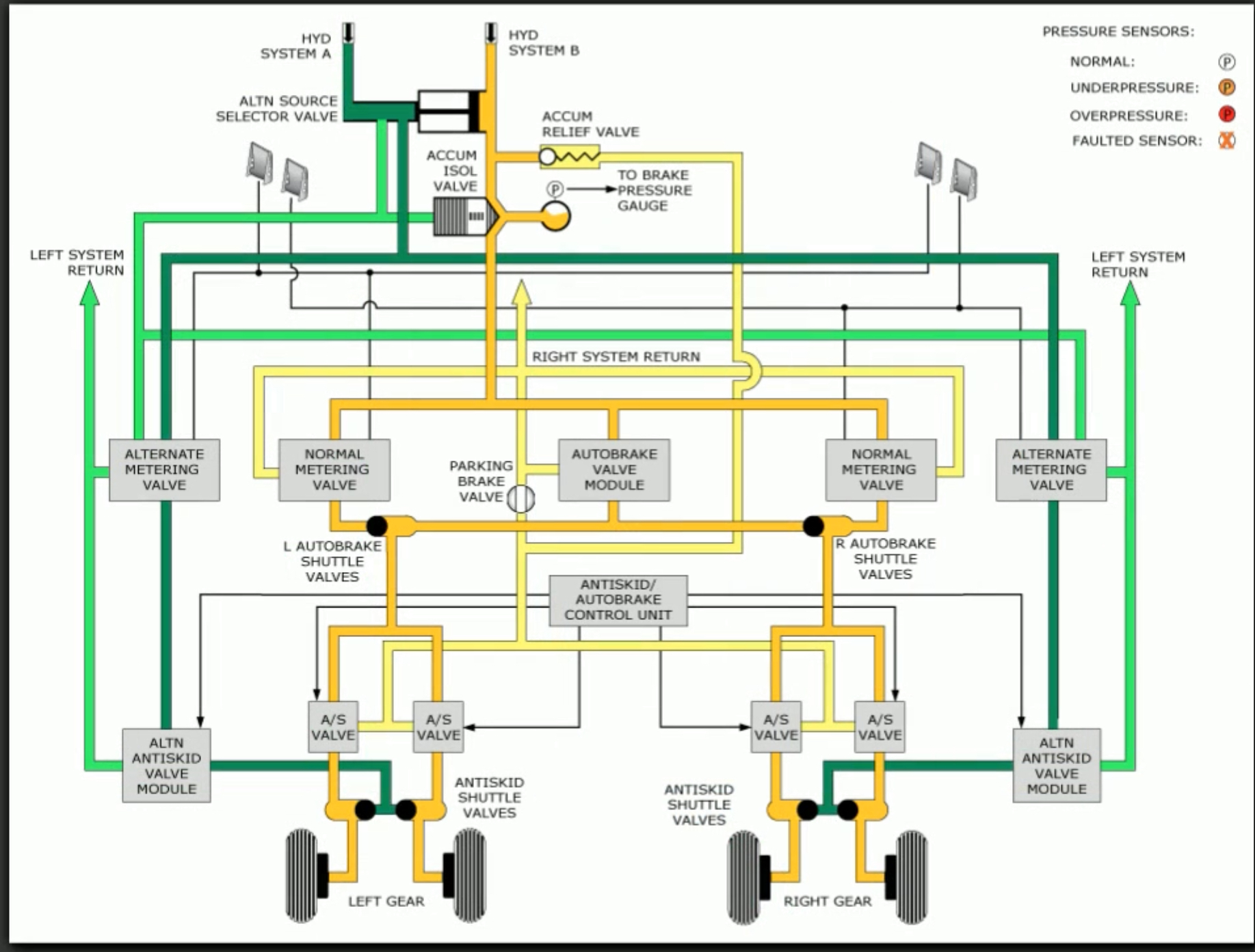
Brake application and accumulator
Pressing a brake pedal proportionately opens a metering valve that allows pressurised hydraulic fluid to pass through the anti-skid module and then to the brake disks. When using system A, the system uses alternate metering valves and anti-skid modules to operate the brakes, although auto-brakes are unavailable.
The alternate brake system is also used to stop wheel rotation prior to retraction into the wheel well.
Additionally, should both hydraulic systems fail, you can get several brake applications or one parking brake application from trapped hydraulic pressure in the accumulators. This also means that the auto-brake system is inoperative.
The accumulator is pre-charged to 1,000 psi and further pressurised by system B. Normal pressure is 3,000 psi, while max pressure is 3,500 psi as indicated by the green arc in the brake pressure indicator.
Anti skid
Anti-skid functions with either system A or B. The normal system provides protection to each individual wheel, while the alternate system provides protection to laterally paired wheels instead of individual ones.
The system works by allow the anti-skid valve to reduce brake pressure whenever a skid is detected. This continues until the skidding stops.
The only flight deck indication related to the anti-skid system is the ANTISKID INOP light. Note that in addition to anti-skid, the auto-brake system will be inoperative.
Auto-brake
The auto-brake system uses system B pressure, and provides:
- Maximum deceleration for rejected takeoffs
- Automatic braking at pre-selected acceleration rates immediately after touchdown
- the system brings aircraft to a full stop.
Although the auto-brake system will bring the aircraft to a full stop, it can be disarmed and overridden by manually applying brakes.
The auto-brake select switch on the forward panel controls the Rejected Takeoff (RTO) mode and the Landing Modes. Note that to select the MAX auto-brake setting, the switch must be pulled out.
The auto-brake system disarms during any of the following: ?
- Speed brake lever moved to the
DOWNdetent during RTO or landing - Manual brakes applied
- Thrust levers advanced during RTO or landing (if within 3 sec of touch down, no light will illuminate)
- Landing with RTO selected
- Moving selector to
OFF - Any malfunction
The auto-brake system is not available with the alternate brake system.
RTO Mode
To arm RTO Mode:
- Aircraft on ground
- Wheel speed <60 kts
- anti-skid and auto-brake operational
- Switch set to RTO
- Thrust levers at idle
During a takeoff attempt, the RTO mode will apply maximum braking when thrust levers are retarded to idle at or above 90 kts.
Landing modes
There are four levels of deceleration that can be selected by the auto-brake system, 1, 2, 3, and MAX. Note that max auto-brake deceleration is less than that produced by applying full pedal braking.
Auto-brake application begins when:
- Both thrust levers at idle
- Main wheels spin up
Auto-brake pressure is slowly reduced during the landing roll as other controls, such as reversers and spoilers, contribute to deceleration.
Parking brake
Can be set with either system A or B pressurised. It can also be set from the accumulator, although this will bleed all accumulator pressure.
A fault in the parking brake system may illuminate the ANTISKID INOP light.
What does the landing gear lever OFF position do?::Removes hydraulic pressure from the landing gear system.
How many degrees can the nose wheel be turned using the rudder pedals?::7 degrees.
Can you use auto-brakes when hydraulic system B fails?::No, but anti-skid remains operative.
Can you brake if both normal and alternate brake systems fail?::Yes, you get several brake applications or one parking brake application from trapped hydraulic pressure in the accumulators.
How is the hydraulic brake accumulator pressurised?::It is pre-charged to 1,000 psi and further pressurised by hydraulic system B.
What’s the difference between normal and alternate anti-skid systems?::Normal system provides anti-skid to each individual gear wheel, while the alternate system provides protection to laterally paired wheels.
In addition to anti-skid, what else is inoperative if the ANTI SKID INOP light is on?::The auto-brake system.
How is the auto-brake system disarmed after landing?::By manual brake application.
When does the auto-brake RTO mode engage?::When thrust levers moved to idle at or above 90 kts on takeoff.
The normal brake system is powered by which hydraulic system?::System B.
Each landing gear unit is equipped with two air/ground sensors.::True.
What hydraulic system provides pressure for normal landing gear extension and retraction?::System A.
What actions must be accomplished to activate the alternate brake system if hydraulic system B fails?::None, it is done automatically.
What does an illuminate red landing gear selector light indicate?::Gear position disagrees with lever selection or below 800 ft RA with both throttles at idle and any gear not down and locked.
What bus powers the alternate gear extension?::None, it is mechanically operated.
What hydraulic system normally powers nose wheel steering?::System A.
What is the maximum movement of the nose wheel using the tiller?::78 degrees.
Which hydraulic system powers the alternate brake system?::System A.
The landing gear warning horn can be silenced if any gear is not down and locked with flaps at 30 degrees.::False. It cannot be silenced with gear not down and locked and any flap >10 or below 200 ft RA with flaps 0 through 10.