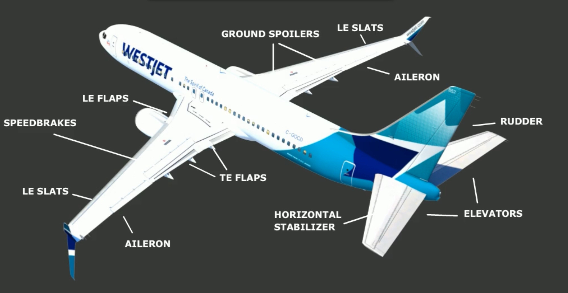
Flight Controls
The primary controls are operated by redundant hydraulic sources, and either hydraulic system A or B can provided pressure to operate all controls. Additionally, the ailerons and elevator can be operated manually if no pressure is available. The rudder may be operated by the standby hydraulic system.
Roll Control
Roll control is provided by two ailerons and 8 flight spoilers. They are controlled by PCUs which are connected by cables to the CA’s and FO’s control wheels. The two control wheels are connected by a cable drive system that allows actuation of ailerons by either wheel.
Ailerons
Moving the control wheels moves cables attached to the PCUs which in turn move the ailerons. The cables are connected there via a the Aileron Feel & Centering Unit, which provides feel force and moves the control wheel to a neutral position when there is no input.
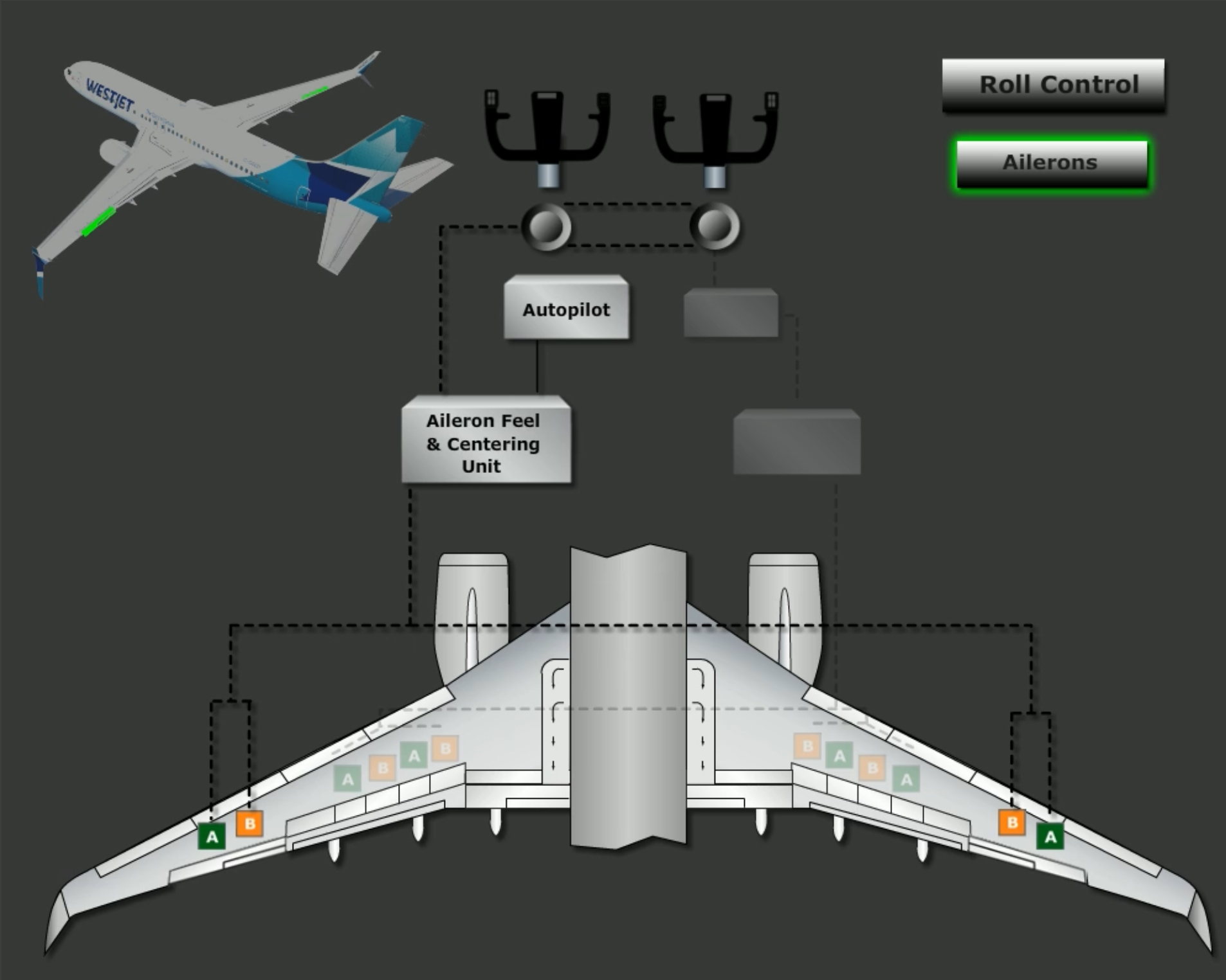
With the autopilot engaged, the FCCs control the aileron autopilot actuators. These give mechanical input to the feel and centering unit as well as aileron position sensor.
Movement of the feel and centering unit is sent to the aileron PCU, while signals from the aileron position sensor go to the FCCs. Should a loss of hydraulic pressure occur, roll control can be maintained mechanically by the ailerons, but not the spoilers.
The system also contains a Transfer unit that isolates the aileron system from the flight spoilers should a jam occur. If the control wheel cannot move, the transfer mechanism lets the crew operate the other control wheel. The left control wheel is able to move the ailerons, while the right control wheel is able to move the spoilers.
Roll trims
The roll trims must be pushed simultaneously to actuate aileron trim. They electrically reposition the aileron feel and centering unit, which cause the control wheels to rotate and redefine neutral.
Flight spoilers
There are four flight spoilers located on the upper surface of each wing and also control roll.
Each hydraulic system, A and B, are dedicated to a different set of spoiler pairs to provide isolation and maintain symmetric operation in the case of hydraulic failures.
To provide spoiler movement proportional to aileron movement there is a Spoiler Mixer connected to the aileron cable-drive. This mixer controls the hydraulic PCUs on each spoiler panel. Spoiler deflection is initiated when the control wheel is displaced more than 10 degrees or so. They approach their maximum deployed position when the wheel turns more than 70 degrees.
Additionally, the spoilers deploy symmetrically when the Speedbrake Lever is used beyond the ARMED position.
Pitch Control
Pitch control is provided by two elevators and a movable horizontal stabiliser.
The elevators are hydraulically powered by PCUs connected by cables to the control columns. Much like the roll control system, the pitch control system contains a feel and centering unit that itself is actuated by the autopilot if engaged.
Manual reversion is an operating mode where the elevators can be mechanically positioned by movement of the control columns in case both main hydraulic systems fail.
Feel control is accomplished by the elevator feel computer, which provides simulated aerodynamic forces using airspeed data from the elevator pitot system and stabiliser position.
The feel system is operated using either hydraulic system A or B, whichever one has higher pressure.
In the event of a control system jam there is an override mechanism that allows the control columns to be physically separated. This is accomplished by applying force against the jam to break out either of the control columns. This will allow the free moving column to provided degraded pitch control, although it should be sufficient for landing and flare.
The control system also includes an actuated stabiliser trim cutout switch, which deactivates stabiliser trim anytime the direction of trim is opposite of pressure on the control column. While normally useful, it can be disabled by the STAB TRIM OVRD switch in a scenario where there has been a control jam, as described in above paragraph.
Stabiliser
The horizontal stabiliser is controlled and positioned by a single electric trim motor. The motor is controlled by either the trim switches on the control wheel, by the autopilot, or by the stabiliser trim wheels, with a range of -0.20 to 16.9 units.
The stabiliser can be manually controlled with the trim wheel, or electrically via the trim switches or autopilot. Whenever electric trim is actuated, the trim wheel moves; grasping the trim wheel stops stabiliser motion.
Yaw Control
There is a single rudder powered by the hydraulic system, as well as a digital yaw damper system.
Each set of rudder pedals is mechanically connected to the input levers of the main and standby rudder PCUs via the rudder feel and centering unit.
The main rudder PCU consists of two independent input rods, two individual control valves, and two separate actuators. The standby PCU is controlled by a separate input rod and control valve, and is powered by the standby system.
Because both hydraulic systems A and B actuated the main rudder PCU, there is a Force Fight Monitor system installed that detects opposing pressure between the A and B actuators, which may occur if either system is jammed or disconnected. The FFM is thus used to automatically turn on the Standby Hydraulic pump and open the standby rudder shutoff valve to pressurise the standby rudder PCU.
Rudder trim
Rudder trim is accomplished by adjusting the neutral position of the rudder pedals via the rudder feel and centering unit. Note that an OFF indication on the Rudder Trim indicator the trim system itself is still functional.
Yaw damp
The yaw damper consists of a main and a standby yaw damper. The operation of the damper does not result in rudder pedal movement.
During normal operations, the main damper uses hydraulic system B. Should the system fail, the YAW DAMPER switch automatically moves to OFF, the amber light illuminates, and the switch cannot be reset if any of the following occur:
- Yaw damp system fault
- Yaw damp not responding
B FLT CONTROLswitch not on
During manual reversion (loss of both A and B hydraulics), both FLT CONTROL switches are positioned to STBY RUD, which allows the yaw damp to be reset to on using the standby hydraulic system. In this scenario a small amount of rudder movement is commanded as a function of control wheel input.
Stall Management and Yaw Damper Computers
Computers that manage both yaw dampers. They receive inputs from:
- Both ADIRUs
- Control wheels
YAW DAMPERswitch positionThe SMYD’s provide yaw damp inputs to the main or standby rudder PCU.
Link to original
Either yaw damper can provide:
- Roll prevention
- Gust Damping
- Turn coordination
The yaw damper can be overridden using rudder pedals or trim inputs.
Trim Systems
The electric and autopilot trim systems have two modes:
- High Speed → Flaps extended
- Low Speed → Flaps retracted
As the airplane speed approaches Mach 1, the centre of lift moves aft and the airplane begins to nose down. A Mach Trim system provides trim stability at high speeds, and is engaged above Mach .615. It functions by adjusting the elevators with respect to the stabiliser as speed increases.
The Mach trim actuator position is calculated by the FCCs. It works by readjusting the normal control wheel position via the elevator feel & centering unit.
Speed Trim System
The aircraft is equipped with a Speed Trim System, or STS. It is designed to improve flight characteristics during:
- Low gross weight
- Aft centre of gravity
- High thrust w/o autopilot
Its purpose is to return the aircraft to a trimmed speed by commanding the stabiliser in a direction opposite the speed change. It uses the autopilot stabiliser trim and increases control column forces to force the airplane to trimmed speeds. As the trimmed speed is returned, the STS commanded stabiliser movement is removed.
Additionally, stall control is also enhanced with the STS. As airspeed decreases, the STS will trim the stabiliser nose down.
Conditions for its operation are:
- Airspeed between 100 kts and Mach 0.60 within 10 seconds of takeoff
- 5 seconds following release of trim switches
- Autopilot not engaged
- Sensing of trim requirement
The system monitors:
- Stabiliser position
- Thrust lever position
- Airspeed
- Vertical speed
The conditions for STS operation include:
Link to original
- Speed < Mach 0.68
- 10 seconds after takeoff
- 5 seconds following release of main electric stab trim switches
- Autopilot not engaged
- Sensing trim requirement
Speed Brakes
In flight
The flight spoiler panels are used as speed breaks to increase drag and reduce lift (note that the ground spoilers do not extend in flight). Using the SPEED BRAKE lever in flight causes all flight spoiler panels to rise symmetrically.
Note that their operation should be avoided in a turn, as they will sharply increase roll rate.
The maximum extended position in flight can be set using the FLIGHT DETENT position. Moving the speed brake lever beyond the detent in flight will cause buffeting, and is prohibited in flight. Addditionally, the speed breaks should not be used in flight below 1,000 ft radalt.
On ground
Ground operation of the system is more automated. The auto system operates on landing when:
SPEED BRAKElever isARMEDARMEDlight illuminate- Radalt <10 ft
- Thrust levers idle
- Main wheels spinning >60 kts
- Landing gear strut compression on touchdown
Note that compression of any gear deploys the flight spoilers; compression of the right gear is necessary to also deploy the ground spoilers.
Under these conditions, the SPEED BRAKE lever automatically moves to the UP position and the spoilers deploy. They all extended to maximum.
The speed brakes will also operate if the lever is in the DOWN position during landing or a rejected takeoff with the following conditions:
- Main wheel >60 kts
- Thrust levers IDLE
- Reverse thrust set to reverse thrust.
After an RTO or landing, if either thrust lever is advanced the lever automatically moves to the DOWN position and all spoilers retract.
High Lift Devices
Trailing Edge devices and Leading edge devices are normally extended and retracted by hydraulic system B. With the flap lever in the UP position, all LE and TE devices are commanded to the retracted position.
The LE FLAPS TRANSIT and LE FLAPS EXT illuminate whenever an LE is in transit or extended respectively. The positions of each individual device can be determined from the Flap Position Indicator and the Leading Edge Devices Annunciator.
LE deployment is sequenced as a function of TE flaps deployment.
When flaps are set between 1 and 25, the LE flaps move to full extended position, while the slats move to the extended position. Beyond flaps 25, the slats move to fully extended (note that non short field performance -800 series the LE Slats extend fully beyond Flap 10).
| Flap Lever position | TE Flap position | LE Flap position | LE Slat position |
|---|---|---|---|
| 1 - 25 | 1 - 25 | Full extend | Extend |
| >25 | >25 | Full extend | Full extend |
| >10 (non short field performance series) | >10 | Full extend | Full extend |
Upon retraction the above sequence is reversed.
Standby mode
The TE devices can be operated electrically by a motor using the alternate flap switches. Using this system also locks out the hydraulic systems to prevent TE flap locks - however, the mode uses the standby hydraulic system to operate the LE flaps and slats.
Although the TE flap position can be controlled up and down by the ALTERNATE FLAPS up/down switch, momentary actuation of the switch causes the LE flaps to fully extended; the alternate flap system cannot retract the LE flaps using the standby hydraulics.
Trailing Edge devices
The trailing edge flaps are double slotted and positioned inboard and outboard of each engine. They are powered by hydraulic system B and varies between settings 1 and 40.
Flap positions 1 - 15 provide increased lift; beyond 15 the flaps provide increased lift and drag.
For landing, the normal positions are 30 or 40. 15 can be used for non-normal landings as directed by checklist. The flaps should not be operated above FL200.
Additionally, holding in icing conditions with flaps extended is prohibited.
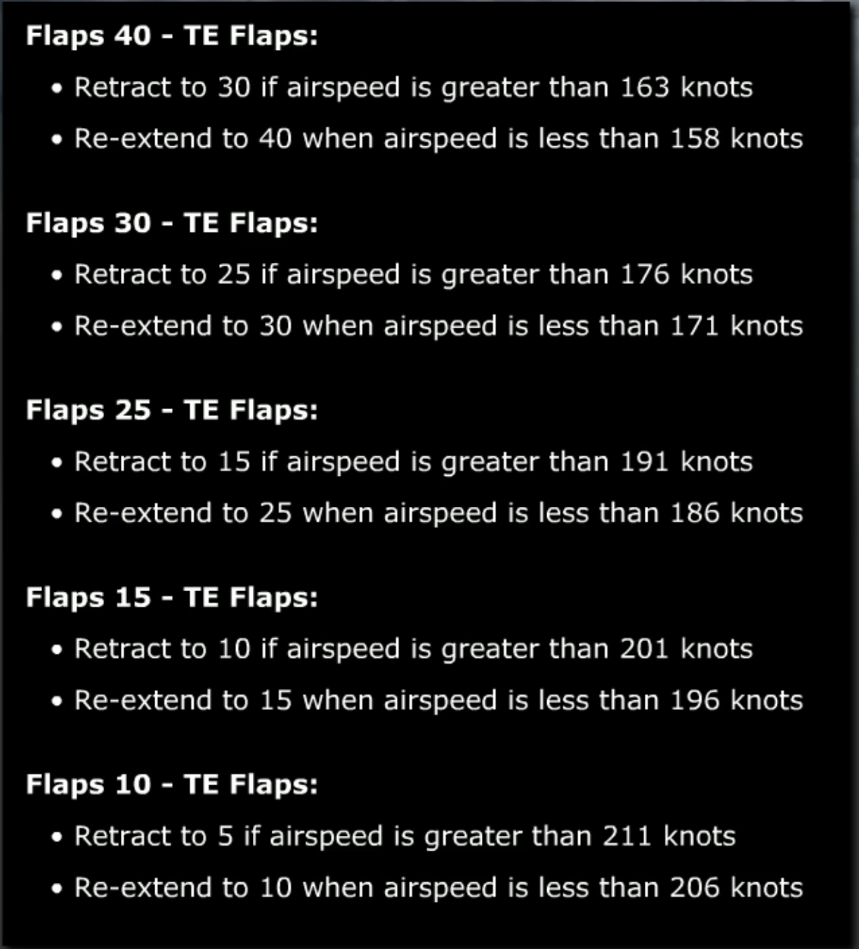
The TE flaps are also equipped with a flight load relief function, that limits the positions of TE flaps as a function of airspeed during normal operation.
It works by retracting and re-extending the flaps as necessary to avoid high loads.
Flap load relief is functional only at flap positions: ?
- 10
- 15
- 25
- 30
- 40
Leading edge devices
LE devices are used to increase performance and lift while reducing stall speed during takeoff and landing. The LE devices consist of four Krueger flaps and eight slats - two flaps inboard of the engines, and four slats outboard of each engine.
Depending on Trailing Edge devices setting, the slats extend to form either sealed or slotted leading edges.
They consist of three positions:
- Up
- Transit
- Extended (only for LE slats, not LE flaps)
- Fully extended
Autoslats
The autoslats are designed to enhance airplane stall characteristics at high AoA during takeoff or approach to landing.
The autoslat commands are calculated by two SMYD computers. It functions by fully extending the LE slats if the aircraft approaches a stall with flaps 1, 2, or 5 (on short field performance series this function works with flaps 1 through 25). Note that this means the slats are already in the extended position.
As the airplane approaches the stall angle, the slats will begin driving to the fully extended position prior to stick shaker activation. Note that LE TRANSIT slats are inhibited during autoslat operation.
Once the AoA is reduces, the slats will return to extended position.
The autoslats are powered by hydraulic system B, but can be powered by system A through a PTU.
When does the Mach Trim system engage?::During flight above Mach 0.615.
What are the normal landing flap positions?::30 and 40.
What is the maximum flap extension altitude?::FL200.
How are the Leading Edge devices controlled?::On a schedule associated with the regular flap lever.
Can the TE flaps be operated in case of complete hydraulic system failure?::Yes, using electric motors with the two alternate flaps switches.
Moving the FLT CONTROL switch to STBY RUD::Activates the standby hydraulic system pump.
Grasping the Stabiliser Trim Wheel stops the electric trim from moving the horizontal stabiliser.::True.
Which LE devices are not monitored for skew conditions?::Slats 1 and 8, as well as LE Flaps.
What controls are mechanically controlled during manual reversion?::Elevator and ailerons.
Hydraulic system ___ controls the normal operation of TE Flaps.::B.
The Yaw Damp system provides ___ .::Gust damping, dutch roll prevention, turn coordination.
The Yaw Damp system is normally operated by___ ::Hydraulic system B.
On a SFP 800 series Slats extend to the full extend position when ___ .::Flap lever is beyond FLAPS 25.
In the event hydraulic system B fails, the LE devices can be retracted after extension during the Alternate Flap Extension method.::False.
With the autopilot engaged, actuating either pair of stabiliser trim switches disengages the autopilot.::True.
If the aileron control system is jammed, force applied to the FO’s control wheel provides control from the ___ .::Flight spoilers.
During Flap Load Relief, when the flaps are set at 30, the TE flaps::Retract to 25 if airspeed exceeds 176 knots.