APU
Provides redundant source of electrical power and auxiliary bleed air.
The APU is a single shaft gas turbine engine located in a fireproof compartment within the tail cone. It operates at a constant speed to drive an electrical generator, pneumatic load compressor, and an accessory gear box.
The bleed air system provides pressurised air to the pneumatic system.
Additionally, the APU has a self-contained oil system to provide lubrication to the bearings, gearbox, and starter-generator.
The start system is comprised of a starter-generator and APU ignition. It is recommended that APU starts be attempted below 10,000 ft.
It can be started and operated for electrical power up to the aircraft’s certified maximum altitude of FL410. APU bleed air can only be used up to 17,000 ft. Bleed air and electrical load combined can only be used up to 10,000 ft.
APU Electrical load
The APU can meet all electrical power demands during ground operations and it can act as an additional power source in-flight. This is done by the single generator in the APU driven by the accessory drive gearbox.
Electrical power from the APU is distributed to the AC Transfer Busses through bus tie breakers. When it’s running but not powering any busses, the APU GEN BUS OFF light is illuminated.
Control of the APU electrical system is done via the APU generator switches, on the Bus Switching Panel:
If neither AC Transfer Bus is powered by an IDG, moving the APU GEN switch to ON: ?
- Connects both AC Transfer Buses to the APU
- Disconnects external power
If both AC Transfer Busses are powered by an IDG, moving the APU GEN switch to ON: ?
- Connects that side’s AC Transfer Bus to the APU (and disconnects it from the IDG)
- Other AC Transfer Bus continues to receive power from the IDG.
Additionally, should an engine failure occur, the APU can provide power to one AC Transfer Bus while an engine generator provides power to the other AC Transfer Bus.
Pneumatic Control
See Pneumatic System.
Fuel and oil
Fuel used for APU operation normally comes from the left side of the fuel manifold when the AC pumps are operating. If AC fuel pumps are not operating, fuel can be suction fed from tank No. 1.
Fuel is automatically heated to prevent icing.
The APU uses its own self-contained oil system for lubrication. There is no direct indication of oil quantity. The system lubricates, cleans, and cools the following: ?
- APU Starter-Gen
- APU Bearings
- APU Gearbox
To cool the oil and air/oil cooler is located in the inlet duct. There is a temperature control valve that manages oil into the cooler or bypasses it to maintain proper temperature.
APU Monitoring and control
The APU is monitored and controlled on the forward overhead panel. It can be started and selected ON by using the APU switch.
It can be monitored with:
- EGT indicator
- Maintenance light
- Low Oil Press Light
- Fault Light
- Over speed light
There is also a single fire detection loop installed next to the APU for fire detection in the compartment. A fire in the APU may be extinguished using a single fire extinguisher bottle located inside the tailcone - note that discharge of this bottle is not automatic.
When the APU is ready to accept bleed air or electrical load, the APU GEN OFF BUS light illuminates. Operate the APU for one full minute prior to use as a bleed air source in order to extend the service life of the unit.
The APU is controlled and monitored by an ECU. The ECU controls APU speed by metering fuel through the electronic fuel control unit. Note that there is no indication of APU speed in the flight deck.
Should the speed or EGT exceed predetermined levels while the APU is providing electrical load only, some electrical load is automatically shed:
- Galley Bus C & D
- 115V AC Main Bus 1
- 115V AC Main Bus 2
- Galley Bus A & B
On the other hand, if bleed air and electrical load raise the EGT levels past the threshold, the ECU reduces bleed air while maintaining electrical load.
Starting and operating.
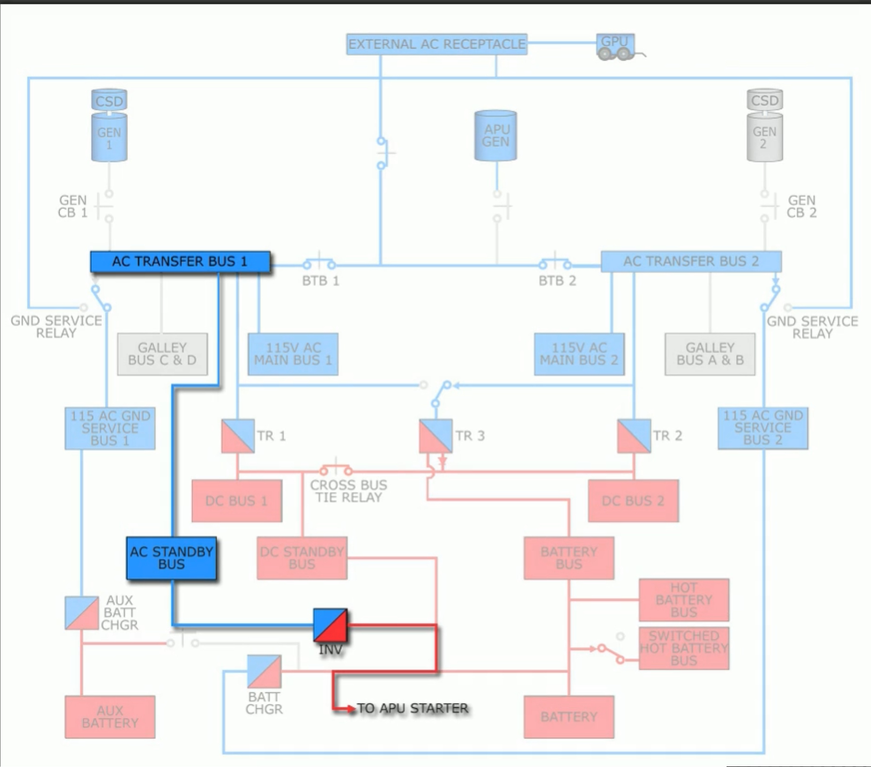
The APU requires electrical power to start and operate. If AC power is available, power to start the APU comes from the No. 1 AC Transfer Bus via the AC standby bus and an inverter.
This AC power can come from either a GPU or an engine driven generator.
If AC power is not available, the APU can be started with the aircraft’s main battery. Note that once the APU is operating the Battery (BAT) switch must remain on. Should the BAT switch be moved to OFF the APU will automatically shutdown as it will lose power of its ECU.

When the APU switch is moved to START the APU begins its automatic start sequence:
- A signal is sent to the ECU
- The fuel shutoff valve opens
- The air inlet door begins to open
- the LOW OIL PRESSURE light illuminates.
When the inlet door is fully open the APU is started.
Types of APU Airflow
There are two types of airflow:
- Combustion Airflow
- Cooling Airflow
Air used for combustion enters the APU via the APU air inlet door. There is no indication on the flight deck regarding the door’s position. Air flows through the inlet and into the compressor of the APU; after combustion, it is exhausted through the outlet at the rear of the aircraft.
Cooling airflow enters from the tail section of the aircraft. As high speed exhaust from the APU exits, a low pressure area is generated; this pulls outside air through an inlet duct that cools down the APU compartment and then passes through the oil cooler. It is then expelled out the APU exhaust duct.
Shutdown modes.
When the APU switch is moved to the OFF position,
- A signal is sent to the ECU
- The APU bleed air valve closes
- The APU generator trips off
- And the APU continues to run for a 60 second cooling period.
- After 60 seconds, the APU shuts down by sending a signal to the ECU.
- The APU air inlet door closes automatically after shutdown.
There is a minimum delay of 2 min 15 seconds after the APU GEN OFF BUS light extinguishes before placing the BATTERY switch OFF.
The APU can also be shutdown using the fire protection system. The APU fire warning switch can be used to shut it down in case of a fire. Additionally, it can also be shutdown from the outside with the APU Fire Control Handle. Pulling either the handle or the fire protection switch shuts down the APU without a 60 second cooling period.
Additionally, the APU has auto shutdown protection for fires, low oil pressure, over speed, and internal faults.
The ECU also provides automatic shutdown protection for the APU. This provides protection for:
- Over speed conditions (Over speed light)
- RPM limit exceeded
- Self-test failed during normal shutdown.
- Low oil pressure (Low Oil Press light)
- Oil pressure is low
- Normal to be illuminated during start
- High oil temp (Fault light)
- APU fires (APU Fire Switch)
- Fuel control unit failures (Fault light)
- EGT exceedance (Fault Light)
- Other system faults (Fault Light)
- Any malfunction exists which has caused the APU to automatically shutdown
When automatic shutdowns occur an associated annunciator light will turn on. These are disarmed when the APU switch is OFF; however, should the light illuminate prior to switching off the APU it will remain illuminated for 5 minutes.
There is a blue MAINT light that indicates a problem with the APU, although it may still be operated given that maintenance has been advised and as per MEL.
What does the APU drive?::An electrical load generator, pneumatic load compressor, and an accessory gear box.
What is the maximum APU operational altitude for electrical power?::The maximum certified altitude, FL410. What is the highest recommended altitude for APU starts?::FL250.
Can you use the APU for electrical load and bleed air at 17,000 ft?::No, bleed air and electrical load combined can only be used up to 10,000 ft.
How do you know when the APU is ready to provide electrical or bleed air load?::When the APU GEN OFF BUS light illuminates. Operate the APU for one full minute prior to use as a bleed air source.
Can you start the APU without external power?::Yes, either AC power from an engine generator via the AC Transfer Bus or from the main battery. What happens if you switch the main battery off after starting the APU?::The APU will shutdown because the APU’s ECU will lose power.
What bus delivers power to the APU from an external power source?::AC Transfer Bus 1, via AC Standby Bus and an inverter.
How long must you wait after shutting down the APU before switching the batteries off?::2 minutes 15 seconds after the APU GEN OFF BUS light extinguishes.
What happens when you put the APU switch to START then OFF?:: ECU receives signal, fuel shutoff valve opens, air inlet door begins to open, LOW OIL PRESS light illuminates. The air inlet door finishes opening once the APU is operational. How can the APU be shutdown?::OFF Switch, Fire Protection Handle, and from the outside via the APU Fire Control Handle.
How is fuel delivered to the APU?::Fuel normally comes from left side of the fuel manifold when AC fuel pumps are operating. Else, fuel can be suction fed from main tank No. 1. How can a fire in the APU compartment be controlled?::It is detected by the fire loop, and can be extinguished by manually activating the single fire bottle in the compartment. The APU operates at a constant speed to meet the aircraft’s electrical demand.::True.